Air conditioner

A kind of air conditioning and air technology, which is applied in the direction of air treatment details, air conditioning system, air treatment equipment, etc., and can solve the problems of complex structure, low degree of freedom in design, loss of compressor input power, etc.

Inactive Publication Date: 2005-10-26
DAIKIN IND LTD
View PDF0 Cites 0 Cited by
  • Summary
  • Abstract
  • Description
  • Claims
  • Application Information

AI Technical Summary

Problems solved by technology

Therefore, the arrangement of the above-mentioned relatively large components is limited, resulting in a problem that the degree of freedom in the design of the entire device is reduced.
[0006] Also, if the seal between the compressor and the expander is not complete, compressed air leakage will occur, and the efficiency will drop significantly due to the loss of compressor input power
Therefore, increasing the number of components installed between the compressor and the expander increases the number of places where air leaks occur, such as connecting parts, and complicates the structure in order to implement a complete seal.

Method used


Image

  • Air conditioner
  • Air conditioner
  • Air conditioner

Examples


Embodiment 1

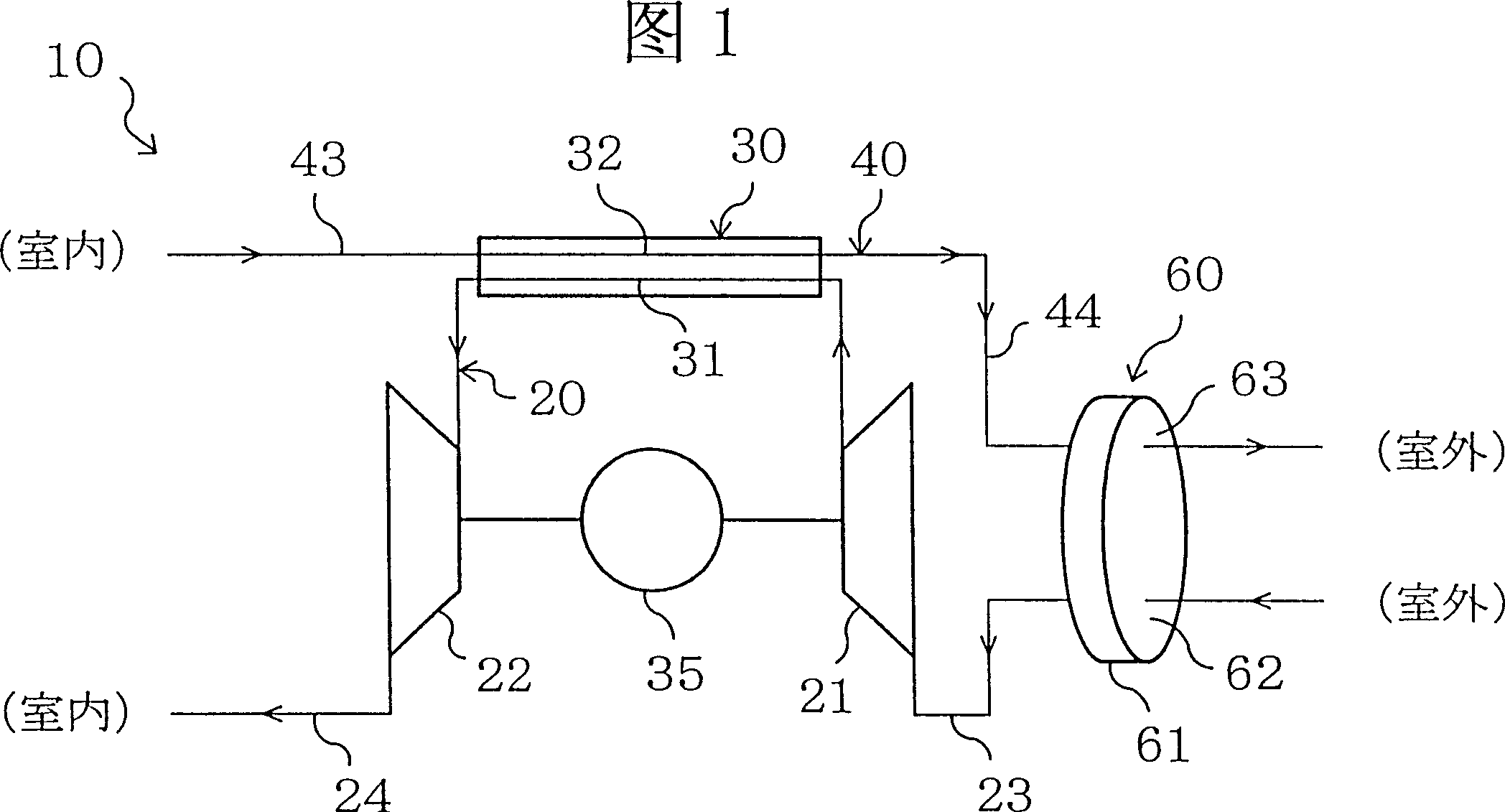
[0104] As shown in FIG. 1 , the air-conditioning device 10 of this embodiment is composed of a first system 20 , a second system 40 , and a dehumidification mechanism 60 as a dehumidification mechanism to cool the room.

[0105] The above-mentioned first system 20 is formed by connecting the compressor 21, the heat exchanger 30, and the expander 22 sequentially through conduits, which can make the first air flow for air circulation refrigeration. The above-mentioned first system 20 is provided with a first inlet conduit 23 connected to the inlet side of the compressor 21 and a first outlet conduit 24 connected to the outlet side of the expander 22 . One end of the first inlet duct 23 is opened to the outside, and outside air as the first air is sucked in. One end of the first outlet duct 24 opens into the room, and guides the low-temperature first air from the expander 22 into the room.

[0106] The above-mentioned second system 40 is configured by connecting the second inlet...

Embodiment 2

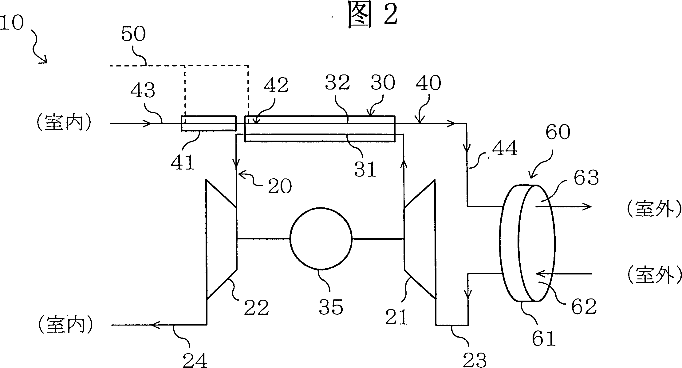
[0125] In the second embodiment of the present invention, the humidification cooler 41 and the water introduction part 42 are provided on the basis of the first embodiment. Other structures are the same as in Embodiment 1.

[0126] As shown in FIG. 2 , the above-mentioned humidification cooler 41 is installed in the middle of the second inlet duct 43 , that is, on the upstream side of the heat exchanger 30 in the second system 40 . In the humidification cooler 41 , a moisture-permeable membrane that allows moisture to permeate is provided, and the moisture-permeable membrane separates and forms an air space and a water space. The second inlet duct 43 is connected to the air space, and the second air flows therein. A water delivery conduit 50 is connected to the water space, and the inside thereof is supplied with channel water and the like. Furthermore, in the humidification cooler 41, the moisture in the water space is supplied to the second air in the air space through the...

Embodiment 3

[0136] Embodiment 3 of the present invention is based on the above-mentioned Embodiment 2, and a preheater 33 is provided, and a heat exchanger 30 is composed of a first heat exchange part 30a and a second heat exchange part 30b. Other structures are the same as in Embodiment 2.

[0137] like Figure 4 As shown, the first heat exchange part 30a and the second heat exchange part 30b of the heat exchanger 30 are respectively provided with a passage 31 on the heat releasing side and a passage 32 on the heat absorbing side. The passage 31 on the heat release side is connected to the compressor 21 on the side of the first heat exchange unit 30a, and connected to the expander 22 on the side of the second heat exchange unit 30b. The passage 32 on the heat-absorbing side is connected to the second inlet pipe 43 on the side of the second heat exchange part 30b, and is connected to the second outlet pipe 44 on the side of the first heat exchange part 30a.

[0138] The above-mentioned ...


PUM


Abstract

An air conditioner using air cycling characterized in that, is formed by sequentially connecting a compressor, a heat exchanger and an expander. In the first channel, an outside air is taken through a first inlet duct and supplied to a room through a first outlet duct. A second channel is formed by connecting both ends of the heat exchanger to ducts. In the second channel, a room air is taken through the second inlet duct and discharged to outdoors through the second outlet duct. A moisture absorbing section of a dehumidifying mechanism is provided in the first inlet duct, while a moisture releasing section thereof is provided in the second inlet duct. A rotor member including a solid adsorbent rotatively moves between the moisture absorbing section and the moisture releasing section. Air dehumidified in the moisture absorbing section is supplied to the compressor.

Description

technical field [0001] The present invention relates to air conditioning devices using air circulation. Background technique [0002] Conventionally, there is a cooling device for air circulation disclosed in JP-A-62-102061. This cooling device is equipped with a compressor, a heat exchanger and an expander. The compressor sucks in air for compression, and the compressed air is cooled by the heat exchanger and expanded in the expander to obtain low-temperature air. [0003] Also, in the cooling device of the above publication, a water vapor separation device using a water vapor separation membrane is provided between the heat exchanger and the expander to separate water from the compressed air fed to the expander. Here, as the air expands through the expander and the temperature becomes lower, water condensation occurs in the air. Therefore, for the air used as the working fluid in the air cycle, it is necessary to dehumidify before entering the expander. For this reason, ...

Claims


Application Information

Patent Timeline
Patent Type & Authority Patents(China)
IPC IPC(8): B64D13/00F24F3/14F24F5/00F25B9/00
CPCB64D13/00F24F5/0085F24F2203/1016F24F3/1423B64D2013/0662F24F2203/1056Y02T50/56F24F2203/1084F24F2203/1068F24F2203/1032Y02T50/50F24F3/1417F24F2203/028
Inventor 朴春成坂本隆一渡部裕司吉见学米本和生
Owner DAIKIN IND LTD
Why Eureka
Try Eureka