Unit for production of track elements

A technology for equipment and components, which is applied in the field of equipment for manufacturing driving road components, and can solve complex problems

Inactive Publication Date: 2005-11-02
奥特玛尔・法里昂
View PDF0 Cites 0 Cited by
  • Summary
  • Abstract
  • Description
  • Claims
  • Application Information

AI Technical Summary

Problems solved by technology

[0004] Although the specific geometry of the individual running surface elements is complex and varied in this way, a high degree of precision is still required in the manufacture

Method used


Image

  • Unit for production of track elements
  • Unit for production of track elements
  • Unit for production of track elements

Examples


Embodiment Construction

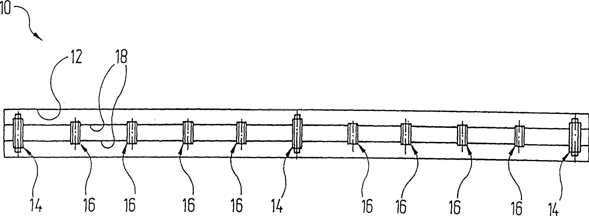
[0027] Equipment for the manufacture of driving pavement elements in figure 1 The whole is indicated by the reference symbol 10 . It comprises an elongated, rectangular depression 12 in plan view in the ground, in which a total of 11 holding devices are arranged along its length.

[0028] Each clamping device at each end of the well 12 as well as the intermediate clamping devices are formed as main support and receiving devices 14 . The clamping devices arranged between two such main bearing and receiving devices 14 are designed as clamping and damping devices 16 . The length of dimple 12 is slightly greater than a running road surface element (in figure 1 not shown in the length). The distance between each clamping device and between the main supporting and receiving device 14 and the clamping and damping device 16 is figure 1 All are equivalent in the shown embodiments. However, they can also vary depending on the type of running surface element to be produced. For thi...


PUM


Abstract

The invention relates to a unit (10) for the production of track elements (32), comprising a number of retaining devices (14), arranged serially in the longitudinal direction of the unit. Said units each comprise a base element (20), which can be moved on wheels (34) and at least one support device (28), connected at least indirectly thereto. The above is arranged, such that a section (30, 172) of a pre-assembled track element (32) may be placed thereon, in the alignment which essentially corresponds to that of the most recent fitting position. Furthermore, the above may be positionally adjusted relative to the base element (20).

Description

technical field [0001] The invention relates to a plant for producing running surface elements. Background technique [0002] The running surface, in particular the railed running surface and here in particular the railed running surface for maglev trains, is assembled from individual running surface elements. The running surface elements known from the market for maglev trains are concrete elements manufactured in situ. In order to facilitate production and reduce production costs, the running track elements should henceforth be prefabricated as metal components in a factory. These metal components are then delivered to the roadway construction site and joined there to one another in such a way that the most continuous course of the roadway is achieved even with different terrains. The running track elements intended for the maglev train project are eg 62m long and are mounted on supports on the ground surface. Among such running surface elements are steel components mad...

Claims


Application Information

Patent Timeline
IPC IPC(8): B23Q3/02B66F5/04E01B25/00E01B25/30E01D21/00E04G21/16
CPCY10T29/53061E01B25/305E01D21/00E01D2101/30Y10T29/53039
Inventor 奥特玛尔·法里昂
Owner 奥特玛尔・法里昂
Why Eureka
Try Eureka