
Positive temp. coefficient thermal resistor

A positive temperature coefficient, thermistor technology, applied in the direction of positive temperature coefficient resistors, resistors, resistor components, etc., can solve the problem of reducing the cost of positive temperature coefficient thermistors, which cannot be fully realized, and it is difficult to metal Problems such as miniaturization of terminals

Inactive Publication Date: 2005-11-02
MURATA MFG CO LTD
View PDF0 Cites 0 Cited by
  • Summary
  • Abstract
  • Description
  • Claims
  • Application Information

AI Technical Summary

Problems solved by technology

However, for the reasons mentioned above, it is difficult to miniaturize the metal terminals, and as a result, the cost reduction of PTC thermistors cannot be sufficiently realized

Method used


Image

  • Positive temp. coefficient thermal resistor
  • Positive temp. coefficient thermal resistor
  • Positive temp. coefficient thermal resistor

Examples


Embodiment Construction

[0040] specific implementation plan

[0041] Now, preferred embodiments of the present invention will be specifically described with reference to the accompanying drawings.

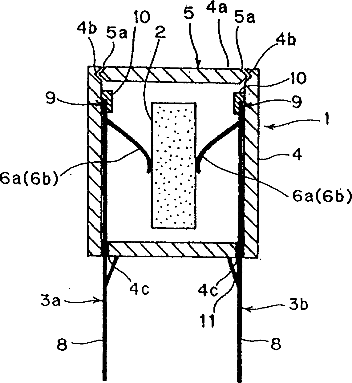
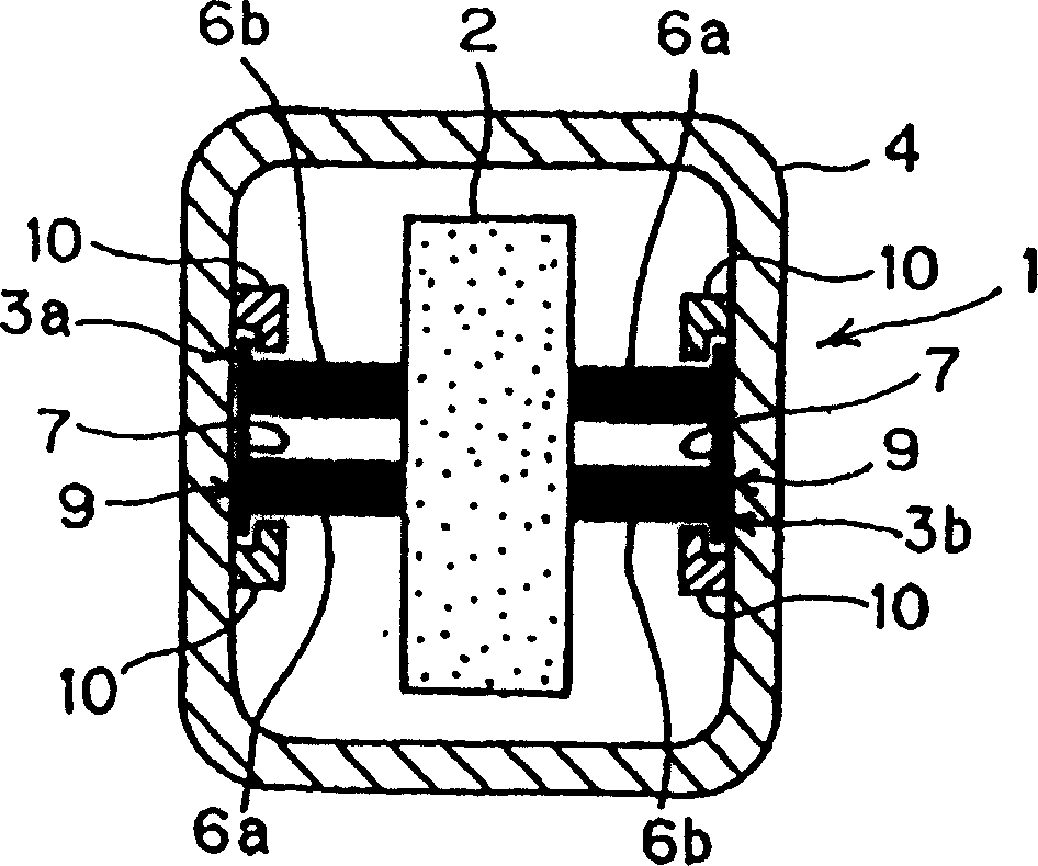
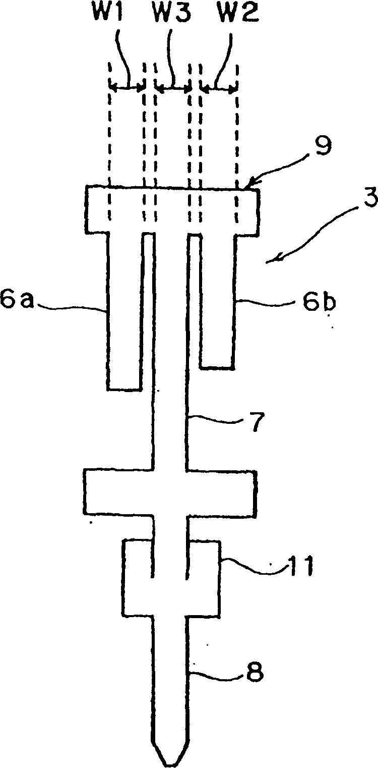
[0042] figure 1 It is the main sectional view of the positive temperature coefficient thermistor according to the preferred embodiment of the present invention. figure 2 It is a planar cross-sectional view of a positive temperature coefficient thermistor. image 3 Illustrated are the metal terminals contained within the PTC thermistor.

[0043] The positive temperature coefficient thermistor is the preferred degaussing positive temperature coefficient thermistor used in the degaussing circuit of the color TV or other corresponding electrical equipment. Such as figure 1 , 2As shown, the positive temperature coefficient thermistor is preferably a two-terminal type positive temperature coefficient thermistor, wherein the plastic case 1 includes a built-in positive temperature coefficient thermistor e...


PUM


Abstract

An inexpensive positive temperature coefficient thermistor has metal terminals which have been miniaturized without deteriorating the characteristics or sacrificing the reliability of the device. The metal terminals include supporting members and springs constructed such that a total width of the supporting members is smaller than a total width of the springs. In addition, connecting portions at the upper ends of the metal terminals engage with a case main body or a covering member to be retained at predetermined positions.

Description

technical field [0001] The invention relates to a preferred positive temperature coefficient thermistor for a degaussing circuit in electrical equipment (such as a color TV). In particular, the present invention relates to a positive temperature coefficient thermistor, wherein the positive temperature coefficient thermistor held by metal terminals is contained in a housing, and the element holding metal terminal part extends to the outside of the housing. Background technique [0002] As an example of background technology, Figure 6 A two-terminal type positive temperature coefficient thermistor is shown. In this PTC thermistor, a PTC thermistor element 22 is sandwiched by a pair of metal terminals 23 a and 23 b and contained in a plastic case 21 . [0003] The casing 21 includes a body 24 having an upper opening and a cover plate 25 covering the opening 24 a of the body 24 . [0004] The metal terminals 23a and 23b are made of elastic metal sheets. Such as Figure 6 , ...

Claims


Application Information

Patent Timeline
Patent Type & Authority Patents(China)
IPC IPC(8): H01C7/02H01C1/14H04N9/29
CPCH04N5/44H01C1/014H01C1/1406H04N9/29H01C7/02
Inventor 田中宏树北村善则
Owner MURATA MFG CO LTD
Learn More