
Current-type synchronous super-class A bias circuit

A bias circuit and current-type technology, which is applied in the direction of electrical components, amplifier parts, amplifiers, etc., can solve the problem that the overall application effect of the super-class A bias compensation circuit is not ideal and reduce the work of super-class A bias compensation Performance, control action errors and other problems, to improve the overall performance, eliminate switching distortion and crossover distortion, the effect of large equivalent impedance

Inactive Publication Date: 2005-11-23
康为民
View PDF0 Cites 0 Cited by
  • Summary
  • Abstract
  • Description
  • Claims
  • Application Information

AI Technical Summary

Problems solved by technology

Voltage sampling causes the sampling signal to be seriously affected by the inductive load speaker, and the control action error is large, or even disordered, which reduces the performance of the bias compensation beyond Class A; the equivalent impedance causes the overload of the front stage to be overloaded, making its performance Severely deteriorated, feeling that the gain outweighs the gain
Therefore, the overall application effect of the existing super class A bias compensation circuit is not ideal

Method used


Image

  • Current-type synchronous super-class A bias circuit
  • Current-type synchronous super-class A bias circuit
  • Current-type synchronous super-class A bias circuit

Examples


Embodiment

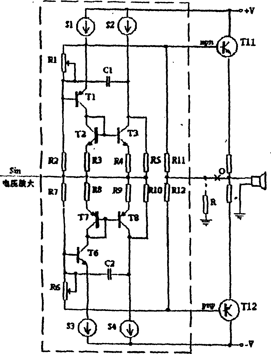
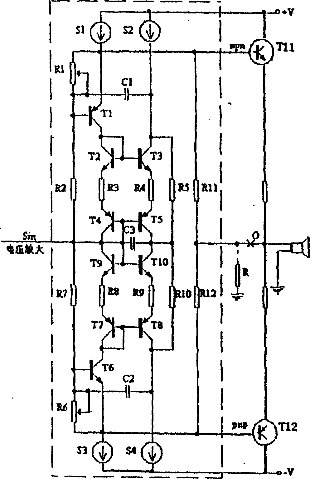
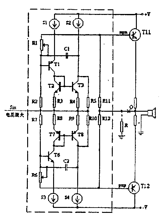
[0009] Embodiment: The composition of the current-type synchronous super-class A bias circuit includes two pairs of constant current sources, two constant voltage bias circuits connected between the two pairs of constant current sources, and two constant voltage bias circuits connected between the two pairs of constant current sources. Two symmetrical mirror constant current sources between them. One pair of constant current sources is composed of constant current sources S1 and S3 with the same parameters, and the other pair of constant current sources is composed of constant current sources S2 and S4 with the same parameters; a constant voltage bias circuit is composed of PNP transistor T1, resistor R1, Composed of R2, the emitter of T1 is connected to the output of constant current source S1 and leads to the positive output terminal npn of the super class A bias circuit, the collector of T1 and NPN transistors T2, T3, resistors R3, R4 form a mirror constant current The coll...


PUM


Abstract

The current-type synchronous super-class A bias circuit includes two pairs of constant-current sources; two constant-voltage bias circuits between the two pairs of constant-current sources; and two symmetrical mirror image constant-current sources between the two constant-voltage bias circuits. The super-class A bias circuit has signal input end in the joint between the two symmetrical mirror image constant-current sources; positive and negative output ends in the two ends of the two constant-voltage bias circuits separately; and the output end for the loudspeaker led out between the positive and negative output ends via two voltage dividing resistors. The present invention has less influence to the front stage, excellent compensation effect and no switching distortion and cross-over distortion.

Description

technical field [0001] The invention relates to a compensation circuit of an audio frequency power amplifier, in particular to a circuit for compensating the final stage signal of the power amplifier. Background technique [0002] How to solve the switching distortion and crossover distortion of the current amplification stage (final stage) in the audio power amplifier when it outputs high power is a long-standing problem. Theoretically speaking, Class A bias compensation is the most effective way to solve this kind of distortion. Class A bias compensation is a kind of dynamic bias compensation. It collects the signal amplitude output by the previous stage at all times and adjusts the bias voltage accordingly. , so that the power transistor at the reverse end (relative to the signal phase) is not cut off at any time within the rated power output range, thereby eliminating switching distortion and crossover distortion. However, the existing application effects of super-class...

Claims


Application Information

Patent Timeline
Patent Type & Authority Patents(China)
IPC IPC(8): H03F1/00H03F1/32H03F3/26
Inventor 康为民
Owner 康为民
Learn More