


Quick Research
Generate reliable direction feasibility study reports for your R&D in just a few steps.

Technical Q&A
Discover and master advanced knowledge NOW. Basics, ideas, possibilities, all at once.

Find Solutions
As an expert in R&D theories, this can generate solutions to your technical problems instantly.

Evaluate Feasibility
Analyze your overall solution with one click, know your potential R&D risks in advance.

Monitor Landscape
Get weekly tech updates, stay abreast of the latest tech innovations and key insights.
Workpiece or tool holders
A fixture and tool technology, applied in the field of fixtures for workpieces or tools, can solve the problem of impossible to use clamping devices, and achieve the effects of sufficient strength, good repeatability and low cost
- Summary
- Abstract
- Description
- Claims
- Application Information
AI Technical Summary
Problems solved by technology
Method used
Image

Examples
Embodiment Construction
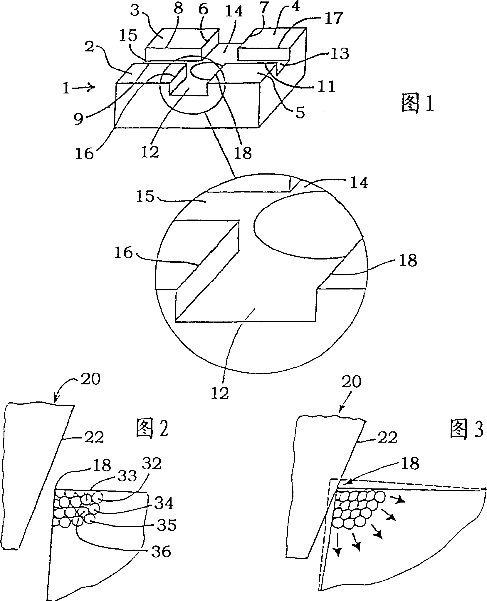
[0022] The holder, generally designated 1 , consists essentially of sintered tool steel, is square in plan view and has a substantially planar outer surface formed by four parts 2 , 3 , 4 and 5 lying in one plane. 10( Figure 8 ) permanently fixes a workpiece or a tool to be machined, such as an electrode for electroerosion machining. Sections 2, 3, 4 and 5 are separated from each other by grooves 12, 13, 14 and 15 made therefrom in the jig. Each groove has a right-angled cross-section with substantially planar groove sides and is arranged crosswise so that two opposing grooves 12 and 14 or 13 and 15 are respectively aligned. The groove width of all the grooves is the same, so that the parallel edges 16, 18 of the opposite groove 12, the parallel edges 11, 17 of the opposite groove 13, the The parallel edges 6, 7 and the parallel edges 8, 9 of the opposite groove 15 have a predetermined distance from one another.
[0023] The chuck, fitted to the fixture 1 , fixed to the ma...
PUM
| Property | Measurement | Unit |
|---|---|---|
| clamping force | aaaaa | aaaaa |
Abstract
Description
Claims
Application Information
 - R&D Engineer
- R&D Manager
- IP Professional
- Industry Leading Data Capabilities
- Powerful AI technology
- Patent DNA Extraction
Browse by: Latest US Patents, China's latest patents, Technical Efficacy Thesaurus, Application Domain, Technology Topic, Popular Technical Reports.
© 2024 PatSnap. All rights reserved.Legal|Privacy policy|Modern Slavery Act Transparency Statement|Sitemap|About US| Contact US: help@patsnap.com