
Drive mechanism for injection device

A technology of driving mechanism and injection device, which is applied in the directions of syringes, auto-injectors, ampoule syringes, etc., to achieve the effect of improving convenience and improving interaction

Inactive Publication Date: 2006-04-05
SANOFI AVENTIS DEUTSCHLAND GMBH
View PDF0 Cites 0 Cited by
  • Summary
  • Abstract
  • Description
  • Claims
  • Application Information

AI Technical Summary

Problems solved by technology

The drive system must also be inherently fail-safe

Method used


Image

  • Drive mechanism for injection device
  • Drive mechanism for injection device
  • Drive mechanism for injection device

Examples


Embodiment Construction

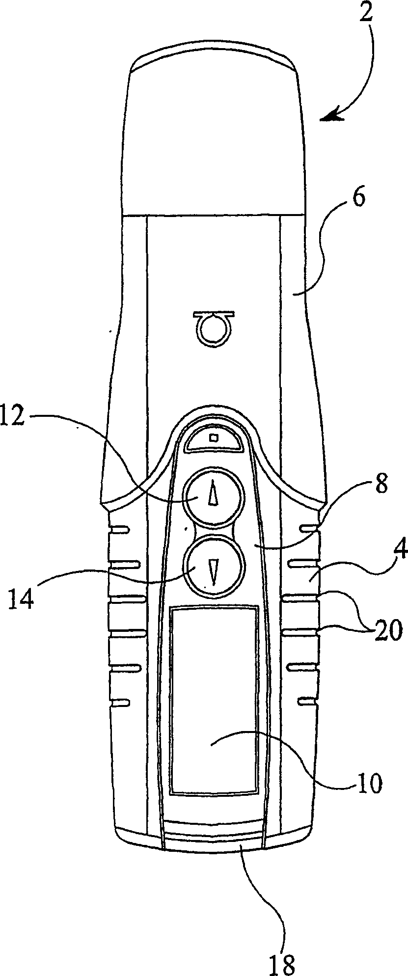
[0014] Refer below Figures 1 to 3 , the pen-type syringe 2 of the present invention can be seen, the syringe 2 comprising a main housing 4 on which an end cap or cap 6 is releasably mounted.

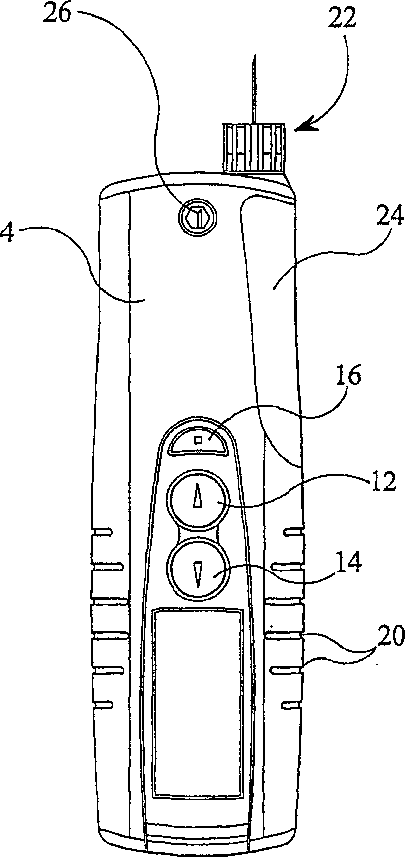
[0015] At a first end of the main housing 4 a control panel area 8 is provided. This area includes a display panel 10, typically an LCD display, and a first dose button 12 and a second dose button 14 operable to increase or decrease the dose of medicament to be released. The control panel area 10 in the illustrated embodiment also includes a supply button 16 .

[0016] Also provided at the first end of the main housing is a dispensing button 18 which is preferably flush with the main housing 4 when not depressed.

[0017] Along the longitudinal axis of the injector 2 , each side of the control panel area 10 is provided with a plurality of grooves or notches 20 . This helps the user to hold the syringe 2 .

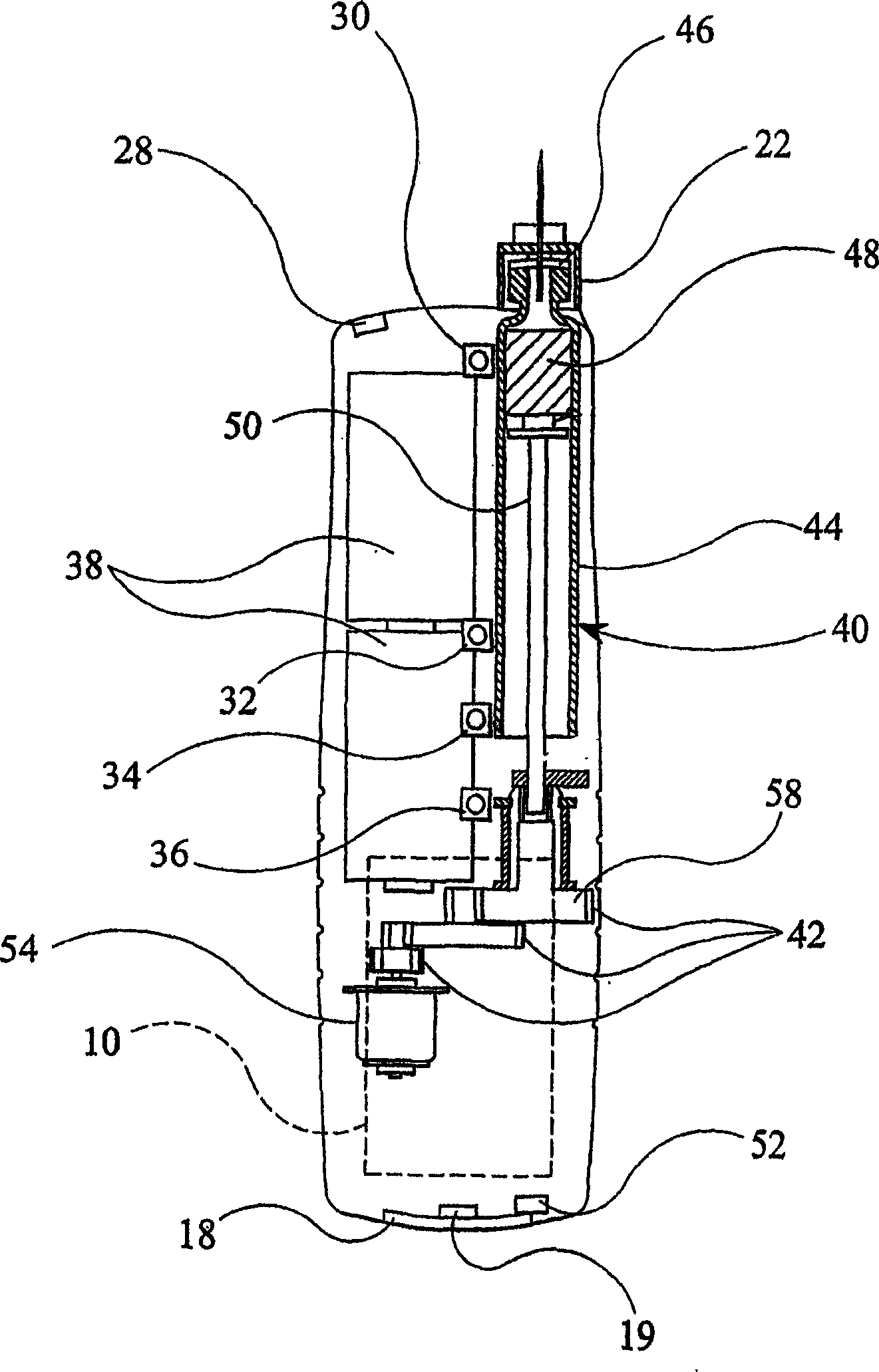
[0018] At the second end of the main housing 4, a needle unit 22 is releasab...


PUM


Abstract

An injection device having a drive mechanism 42 to expel selectively a dose of medicament from a medicament cartridge 40 through a needle unit 22 is disclosed. The injection device further comprises an electronic control unit to control the drive mechanism 42, and a dispense button 18 to generate a dispense button signal to the electronic control unit indicative of the dose to be expelled in which an arm button 16 causes a first arm button signal to be sent to the electronic control unit to permit the dose to be expelled.

Description

technical field [0001] The present invention relates to improvements in injection devices, and more particularly to improvements in injection devices for dispensing controlled quantities of medicaments. Background technique [0002] Typically, such injection devices are used by people suffering from diabetes in order to administer themselves a dose of insulin or insulin-type medication. It should also be appreciated that such an injection device is also suitable for injecting other medicaments. [0003] Previously, the medicament was administered through the use of a disposable syringe that was first filled with the medicament from a separate vial or other container and then used to inject the medicament. However, there are several problems with such devices. In particular, the device is not suitable for the infirm. Additionally, public use of these syringes is problematic due to their social stigma. [0004] In order to overcome these difficulties, various so-called pen...

Claims


Application Information

Patent Timeline
IPC IPC(8): A61M5/145A61M5/142A61M1/36A61M5/168A61M5/172A61M5/20A61M5/24A61M5/315
CPCA61M2205/50Y10S128/01A61M2205/6018A61M5/31525A61M5/20A61M2205/215A61M2005/31588A61M2205/8206A61M5/14566A61M5/14244A61M5/31546G16H20/17A61M5/24
Inventor 克里斯托弗·N·兰利沙恩·A·戴罗伯特·F·维齐罗伯特·伍斯顿
Owner SANOFI AVENTIS DEUTSCHLAND GMBH
Learn More