

Workover rig
A working machine and engine technology, which is applied to agricultural machinery and implements, agriculture, harvesters, etc., can solve the problems of longer and lower lengths of transmission devices, and achieve the effects of low cost, miniaturization, and compact assembly
- Summary
- Abstract
- Description
- Claims
- Application Information
AI Technical Summary
Problems solved by technology
Method used
Image

Examples
Embodiment Construction
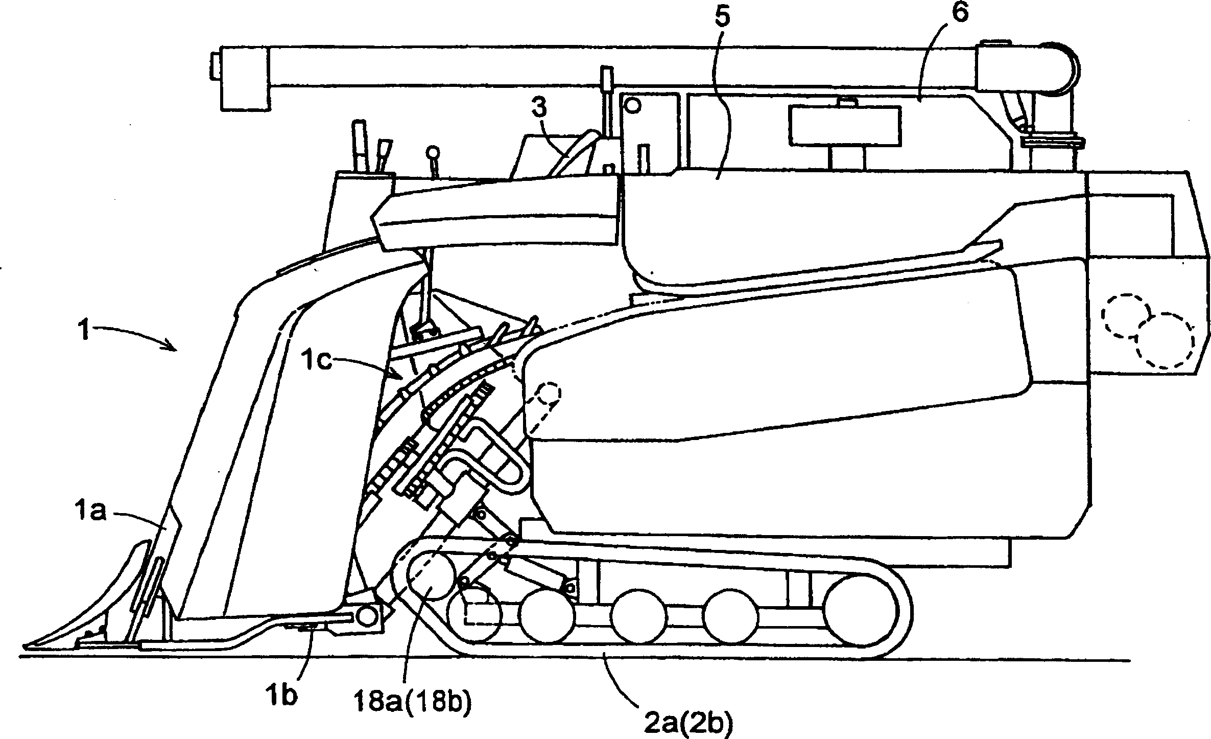
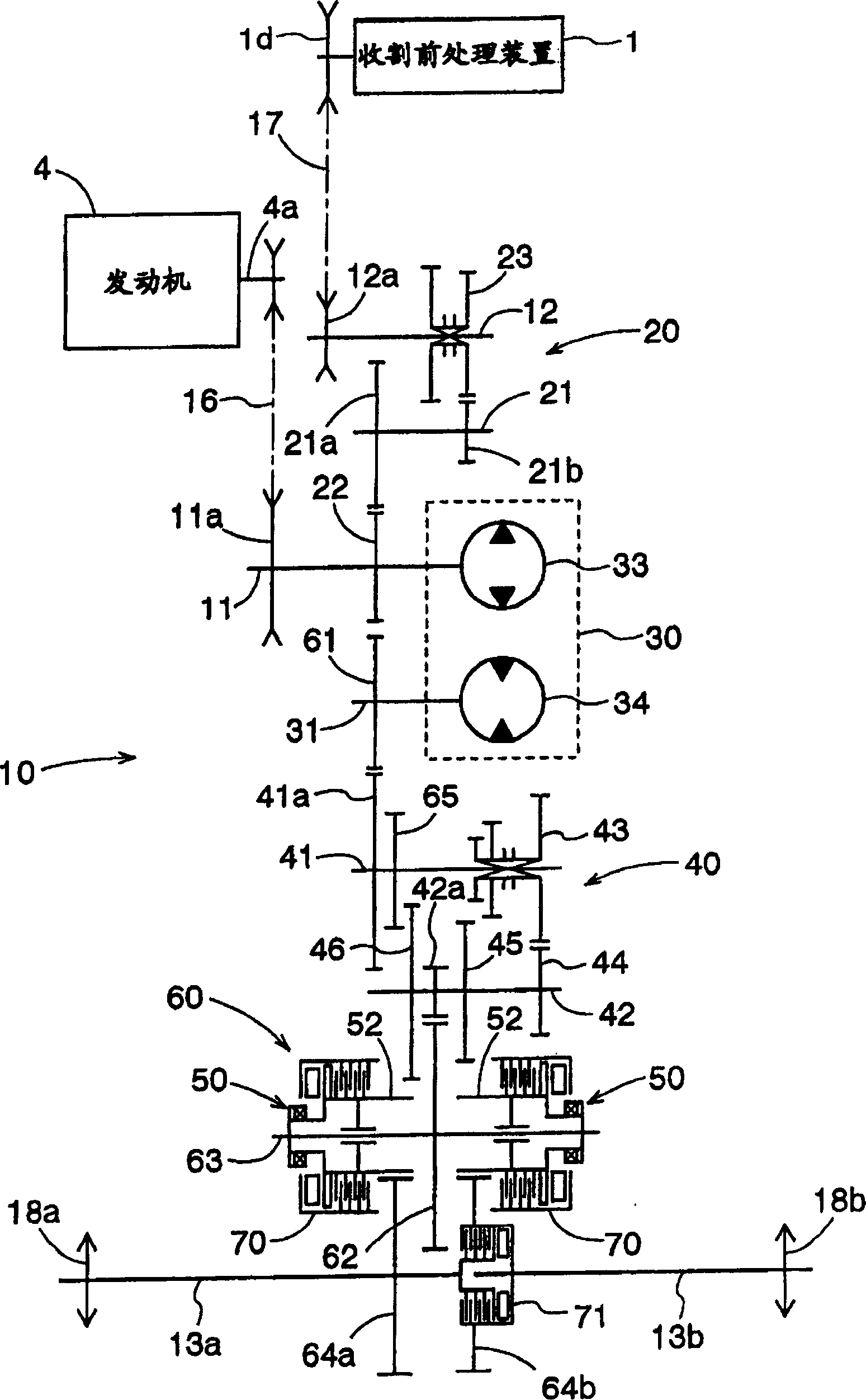
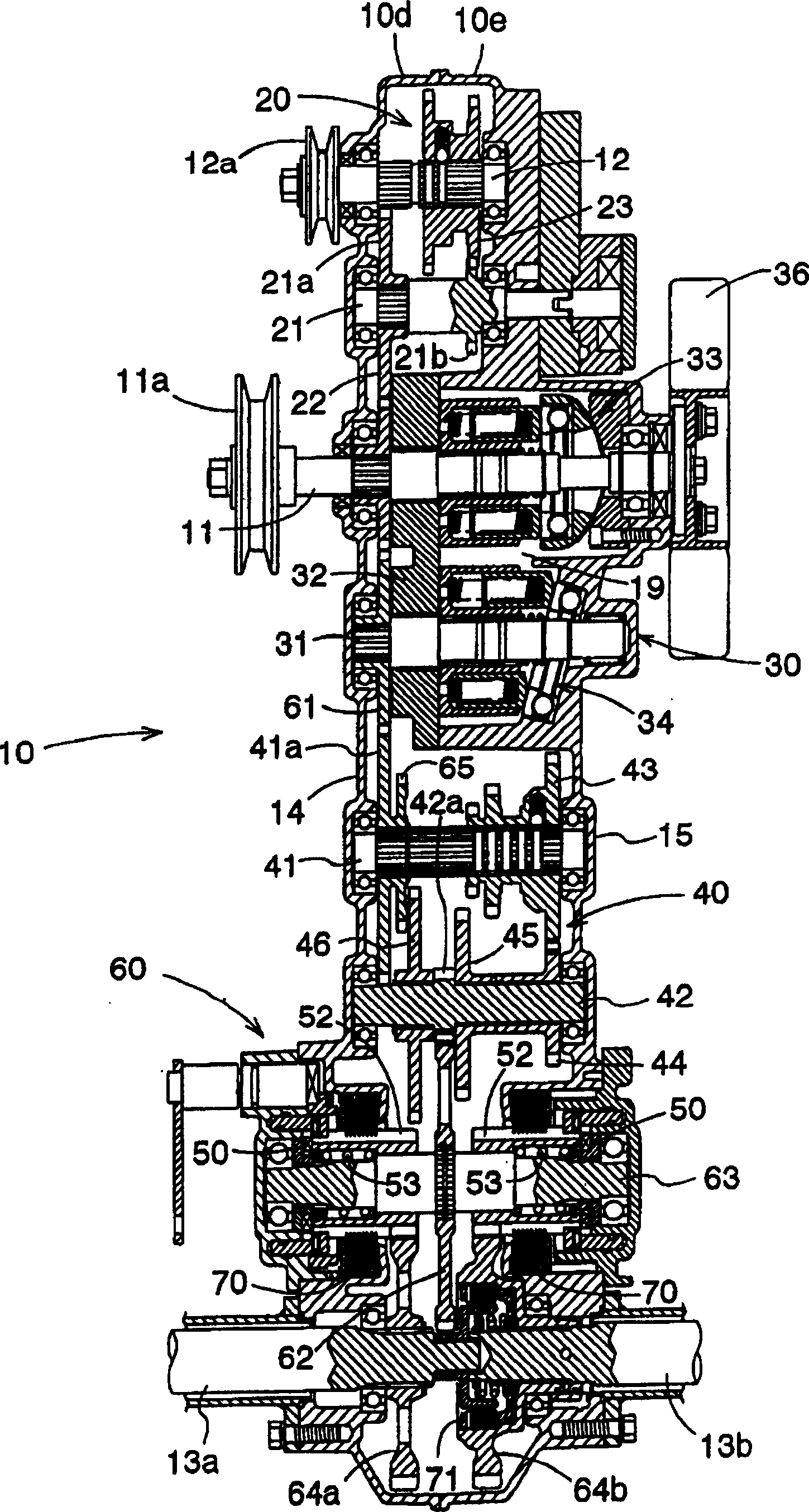
[0046] Below, combine Figure 1 to Figure 8 Embodiments of the work machine according to the present invention are described, and then, in conjunction with figure 1 with Figure 12 to Figure 20 The second embodiment will be described. In all the embodiments, a combine harvester is used as an example of a work machine, and its overall side view is shared. figure 1 . Therefore, for figure 1 It is only described in the first embodiment, and will not be repeated in the second embodiment.
[0047] 1st form of implementation
[0048] figure 1 In the combined harvester shown, No. 1 is a pre-harvest processing device. This pre-harvesting treatment device 1 is carried out by lifting up the ear stalk of erect growth such as rice and wheat, handles the lifting device 1a, the clipper type harvesting device 1b that the ear stalk that lifts up is carried out harvesting process, and the ear stalk that will harvest The conveying device 1c etc. which convey to the rear of the body are ...
PUM
 Abstract
Description
Claims
Application Information