
Apparatus for photoreaction

A photoreaction and reaction technology, applied in laser devices, measuring devices, lasers, etc., can solve the problems of low density, difficult photoreaction, and low reactivity.

Inactive Publication Date: 2006-05-17
铃木康夫 +1
View PDF0 Cites 0 Cited by
  • Summary
  • Abstract
  • Description
  • Claims
  • Application Information

AI Technical Summary

Problems solved by technology

For this reason, the reaction space is minimized both in time and space, and as a result, it becomes difficult for the photoreaction to occur
[0003] However, for the incident gas flow and particle beam to cause photoreaction to occur, a wide hole on the axis (called the aperture) is required as the entrance and exit holes, and most of them have low density and low reactivity.

Method used


Image

  • Apparatus for photoreaction
  • Apparatus for photoreaction
  • Apparatus for photoreaction

Examples


Embodiment Construction

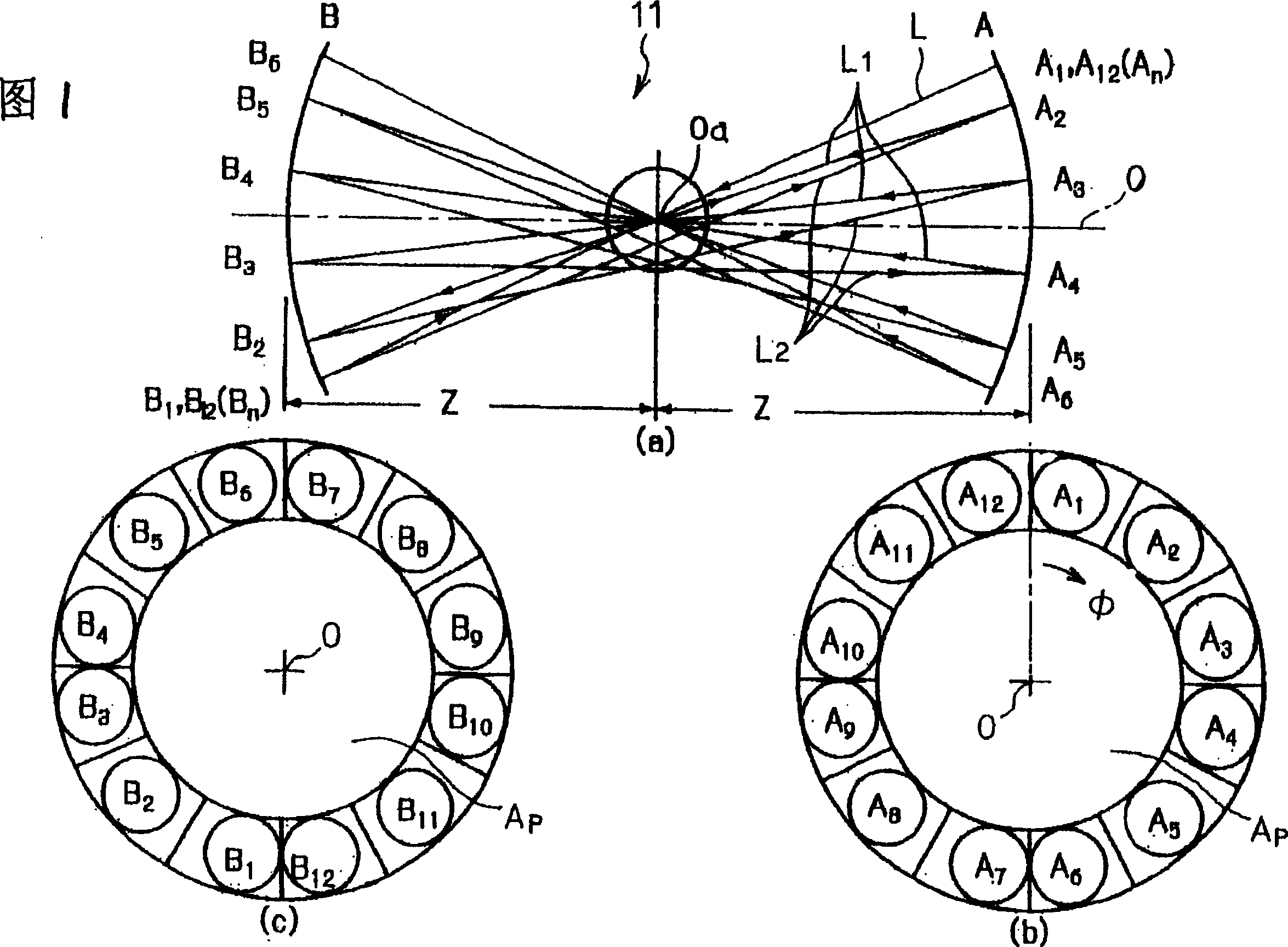
[0017] Embodiments of the present invention will be described with reference to the drawings. Fig. 1 is a diagram showing an overview of the photoreaction device of the present invention, (a) is a side view, and (b) and (c) are front views of respective mirror groups. figure 2 The optical paths L1 and L2 of the laser beams passing between the mirror groups A and B are shown.

[0018] The photoreaction device 11 has a pair of mirror groups A, B placed opposite to each other. The mirror group A is formed by arranging a plurality of concave mirrors A1, A2, . . . , An in a ring around the axis O. The mirror group B is formed by arranging a plurality of concave mirrors B1 , B2 , . . . , Bn in a ring around the axis O. FIG. 1 shows a case where mirror groups A and B each consist of 12 concave mirrors (in the case of n=12). An opening Ap for introducing electron beams is formed inside the rings of the mirror groups A and B. As shown in FIG. In Fig. 1(a), it shows that the mirror ...


PUM


Abstract

The laser light is reflected multiple times by multiple opposing concave mirrors, so that the reflected light path is concentrated to form a reaction space with high photon density, and reaction objects such as gas, liquid, solid, plasma, particle beam, and electron beam are introduced into the In this reaction space, photoreactions such as photoexcitation, photoionization, photolysis, photoseparation, photosynthesis, photogeneration, photoanalysis, etc. are caused by interaction with laser light.

Description

technical field [0001] The present invention relates to multiple reflections of laser light by a plurality of facing concave mirrors, so that the reflection light path is concentrated to form a reaction space with high photon density, and the gas, liquid, solid, plasma, particle beam, electron beam and the like The reaction object is introduced into this reaction space, and through the interaction with the laser, it causes photoreactions such as photoexcitation, photoionization, photolysis, photoseparation, photosynthesis, photogeneration, and photoanalysis. Background technique [0002] Gases, liquids, solids, particle beams, etc. correspond to the atoms and molecules that make up them, and a laser with a specific wavelength undergoes a strong photoreaction. Conventional techniques for performing such a photoreaction generally use an optical resonator in which two curved mirrors are placed opposite each other, and the photoreaction is performed therein. In this case, the s...

Claims


Application Information

Patent Timeline
IPC IPC(8): H01S3/081G01N21/03G01N21/63G21K1/00G21K1/06G21K1/12H01S3/23H05G2/00
CPCG21K1/00G21K1/06G21K1/12H05G2/00H01S3/081
Inventor 铃木康夫池畑隆
Owner 铃木康夫
Learn More