Double scanning thin film processing system

A double-scanning, deposition system technology, applied in vacuum evaporation plating, coating, sputtering plating, etc., can solve problems such as target distance limitation

Inactive Publication Date: 2006-05-24
尤纳克西斯美国公司
View PDF0 Cites 2 Cited by
  • Summary
  • Abstract
  • Description
  • Claims
  • Application Information

AI Technical Summary

Problems solved by technology

However, there are practical limitations on the size of the target and the distance from the target to the

Method used


Image

  • Double scanning thin film processing system
  • Double scanning thin film processing system
  • Double scanning thin film processing system

Examples


Embodiment Construction

[0030] There are many devices that require highly uniform optical film coatings. For example, optical filters used in fiber optic communication system applications may require multiple layers of highly uniform thin films, where each layer has a precise thickness. Optical fiber communication systems are now widely used. Recently, new communication services such as the Internet, high-speed data links, video services, and wireless services have led to a rapid demand for broadband. Currently, data traffic is increasing at a rate of 80% per year, and voice traffic is increasing at a rate of 10% per year.

[0031]One way to increase bandwidth in fiber optic communication systems is to increase the wavelength of light propagating in the fiber. Wavelength Division Multiplexing (WDM) is an optical technique that propagates multiple wavelengths in the same fiber, thus effectively increasing the total bandwidth of each fiber to the sum of the bit rates of each wavelength. A bandwidth ...


PUM


Abstract

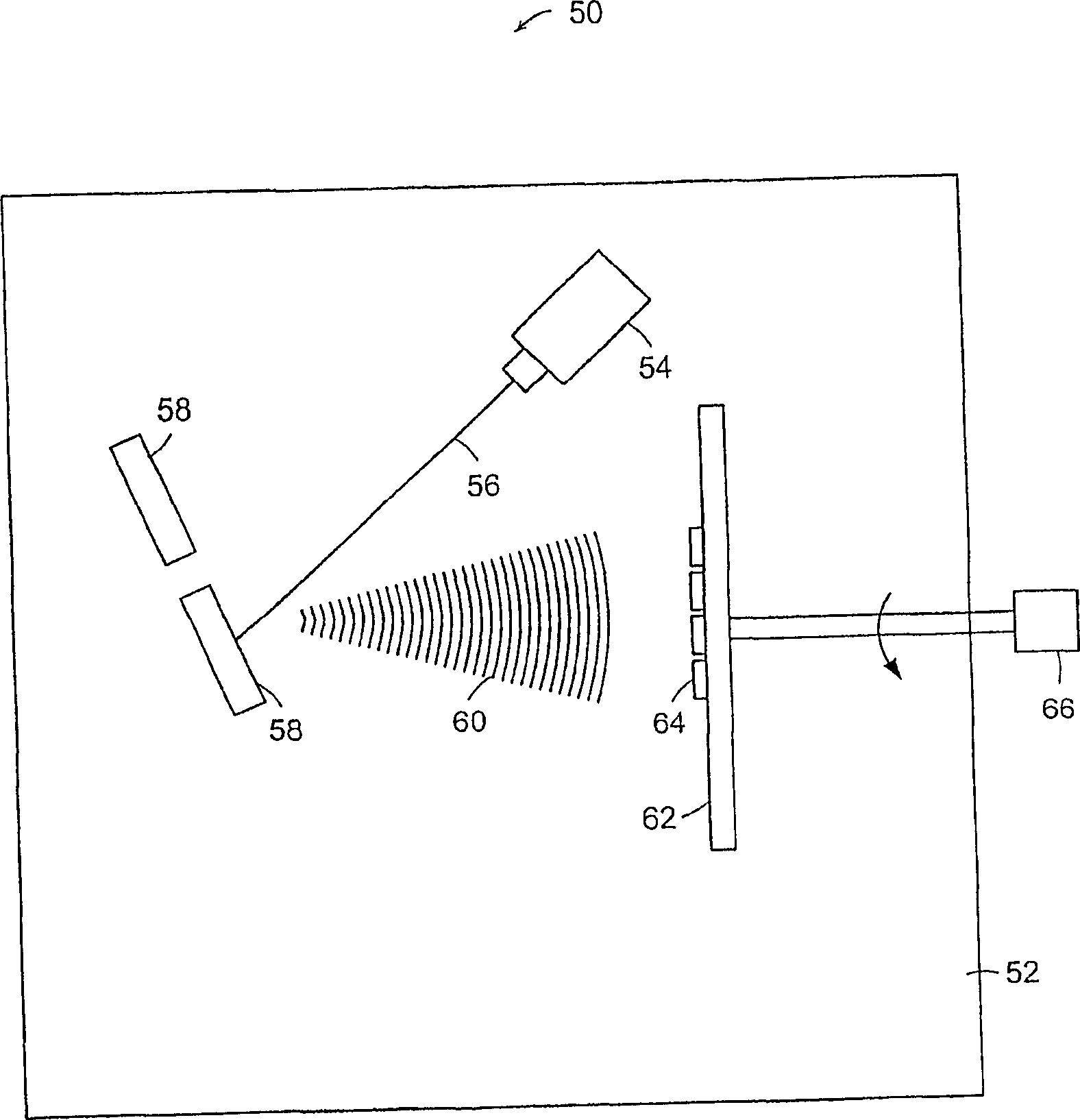
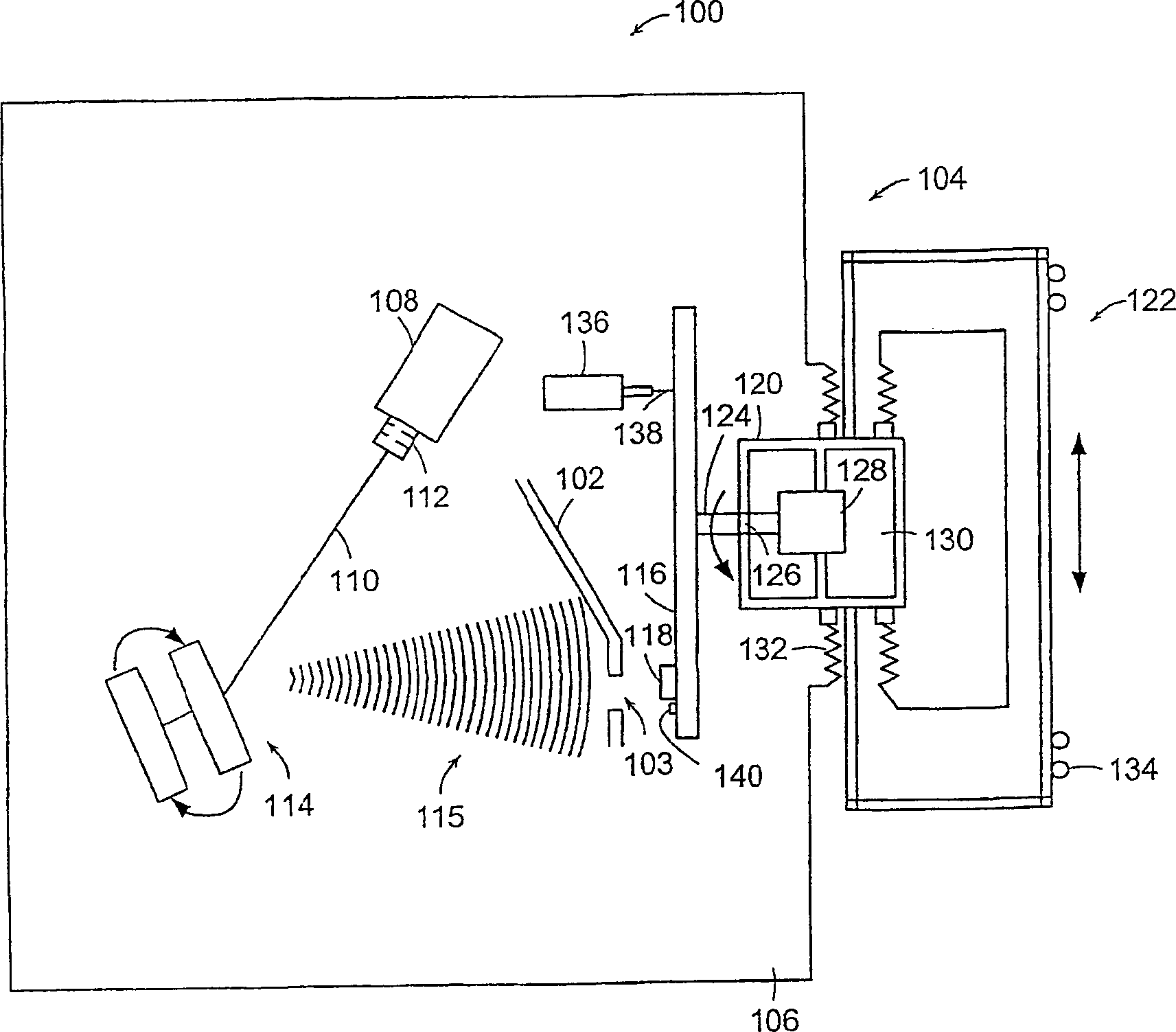
The present invention describes a deposition system. The deposition system includes a deposition source that generates a deposition flux containing neutral atoms and molecules. A shield defining an aperture is located in the path of the deposition flow. The shield passes the deposition flux through the aperture and virtually blocks the deposition flux from propagating anywhere else behind the shield. There is an underlying support near the shield. A dual scanning system utilizes first and second motions to scan the underlying support associated with the well.

Description

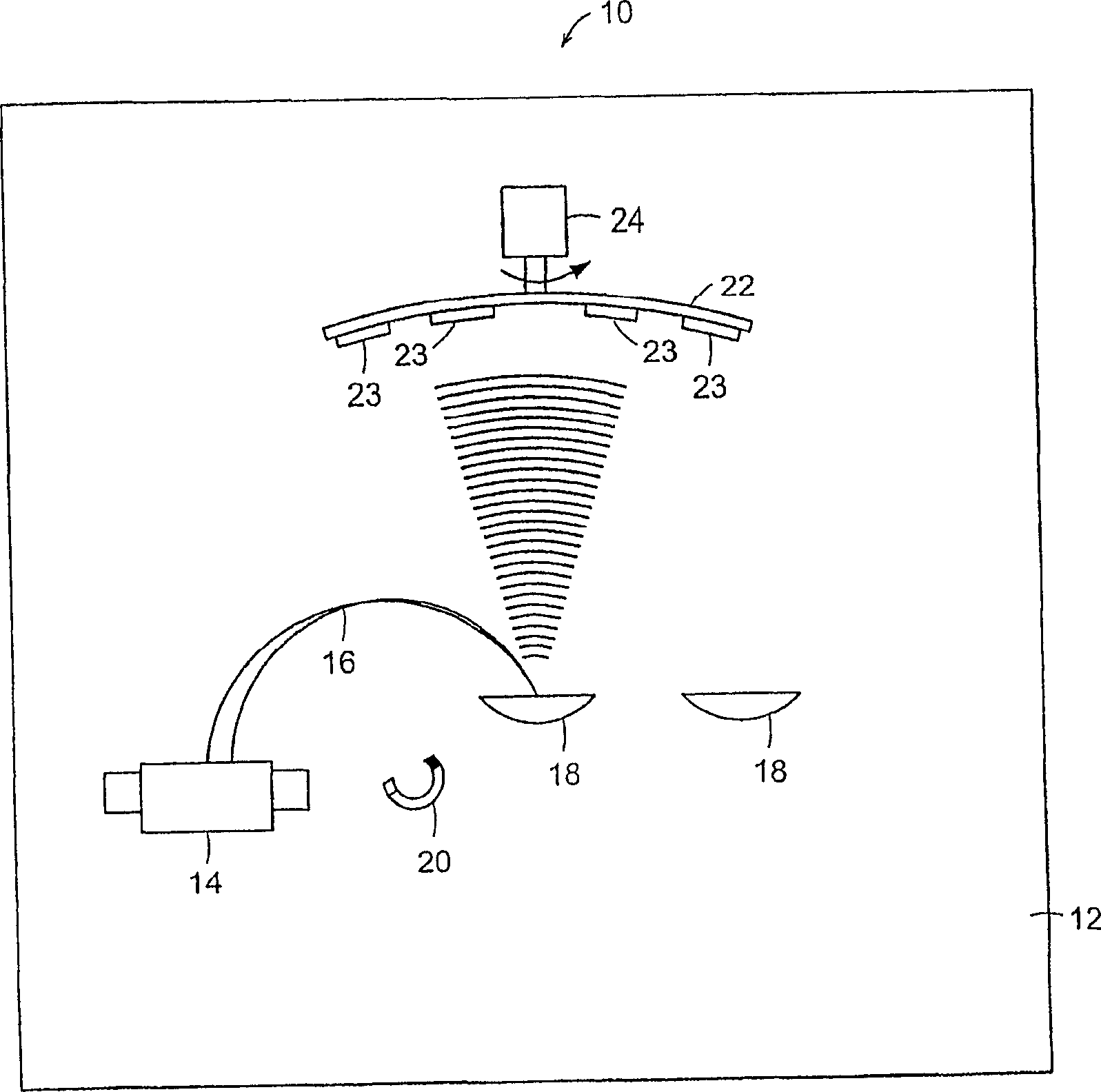
[0001] related application [0002] This application was claimed prior to Provisional Patent Application No. 60 / 217,049, filed July 10, 2000, the entire specification of which is hereby incorporated by reference. This application is also related to Provisional Patent Application No. 60 / 266,114, filed February 2, 2001, the entire specification of which is hereby incorporated by reference. technical field [0003] The present invention generally relates to thin film deposition and etching systems. In particular, the present invention relates to methods and apparatus for depositing thin films very uniformly or etching materials at very uniform etch rates. Background technique [0004] There are generally three techniques for depositing thin films onto substrates. These techniques are evaporation, magnetron sputtering and ion beam deposition. figure 1 A schematic diagram of a prior art electron beam vapor deposition system 10 is shown. The steam system 10 is housed in a vacu...

Claims


Application Information

Patent Timeline
IPC IPC(8): C23C14/46C23C14/04C23C14/54C23C14/35C23C14/50
CPCC23C14/228C23C14/044C23C14/46
Inventor 皮埃罗·斯弗拉佐李中新
Owner 尤纳克西斯美国公司
Why Eureka
Try Eureka