Supercharge Your Innovation With Domain-Expert AI Agents!

Wire bunch wiring structure for piggyback pod

A wiring structure and power cabin technology, applied in the direction of upper structure, power device, upper structure sub-assembly, etc., can solve the problems of increasing production cost and reducing assembly work efficiency, and achieve the effect of improving work efficiency and reducing production cost

Inactive Publication Date: 2006-08-23
NISSAN MOTOR CO LTD
View PDF1 Cites 0 Cited by
  • Summary
  • Abstract
  • Description
  • Claims
  • Application Information

AI Technical Summary

Problems solved by technology

[0007] However, the wire harness wiring structure of the power compartment described in such patent document 1 is due to the different occasions of the specifications of the mounted engine body or the different occasions of the specifications of the gearbox due to the difference in the driving form adopted. Specifications have to change the wiring harness arrangement in the power cabin, so not only the efficiency of assembly is reduced, but also the production cost may be increased

Method used


Image

  • Wire bunch wiring structure for piggyback pod
  • Wire bunch wiring structure for piggyback pod
  • Wire bunch wiring structure for piggyback pod

Examples


Embodiment Construction

[0014] Hereinafter, an embodiment of the present invention will be described in detail together with the accompanying drawings.

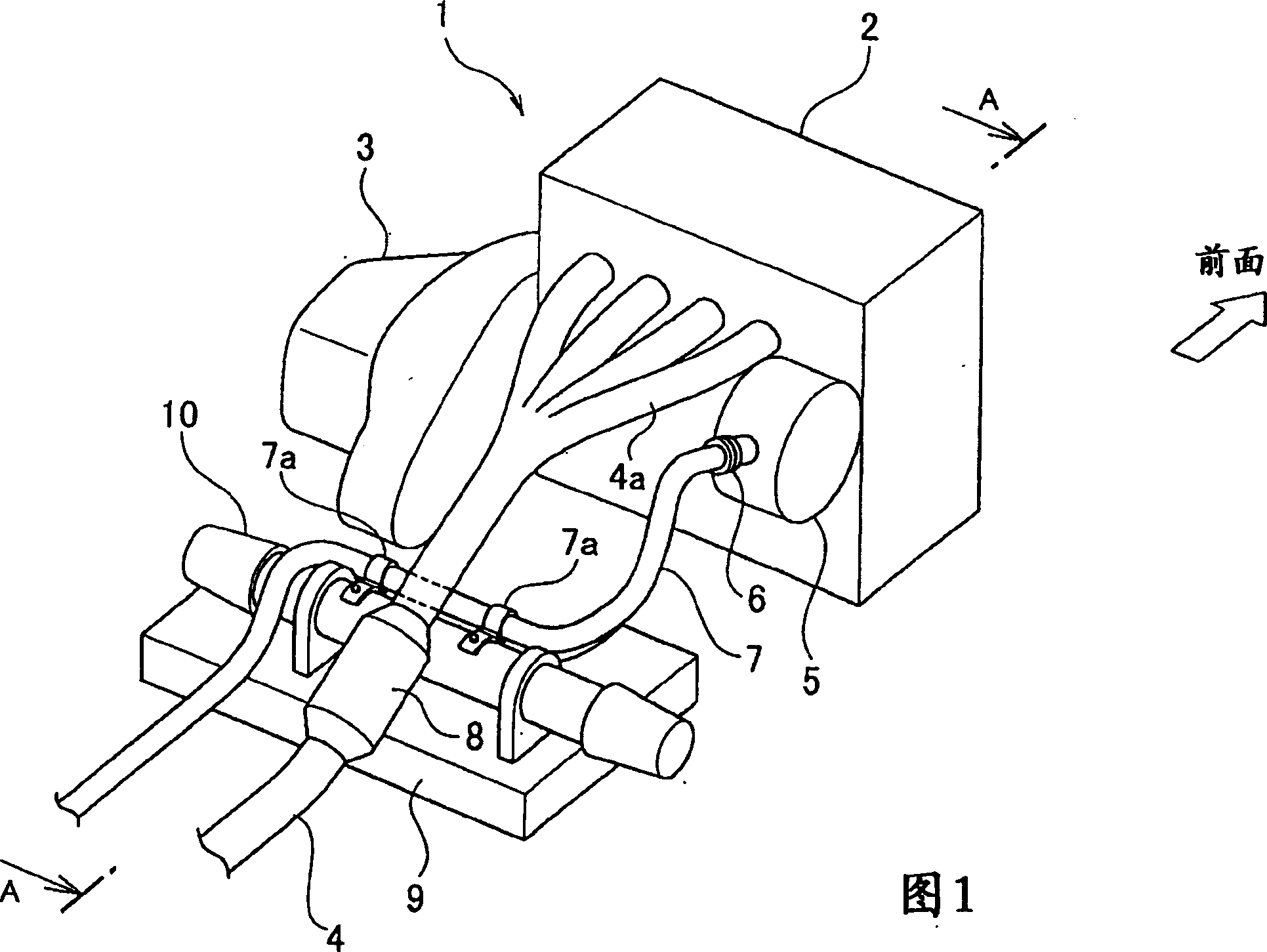
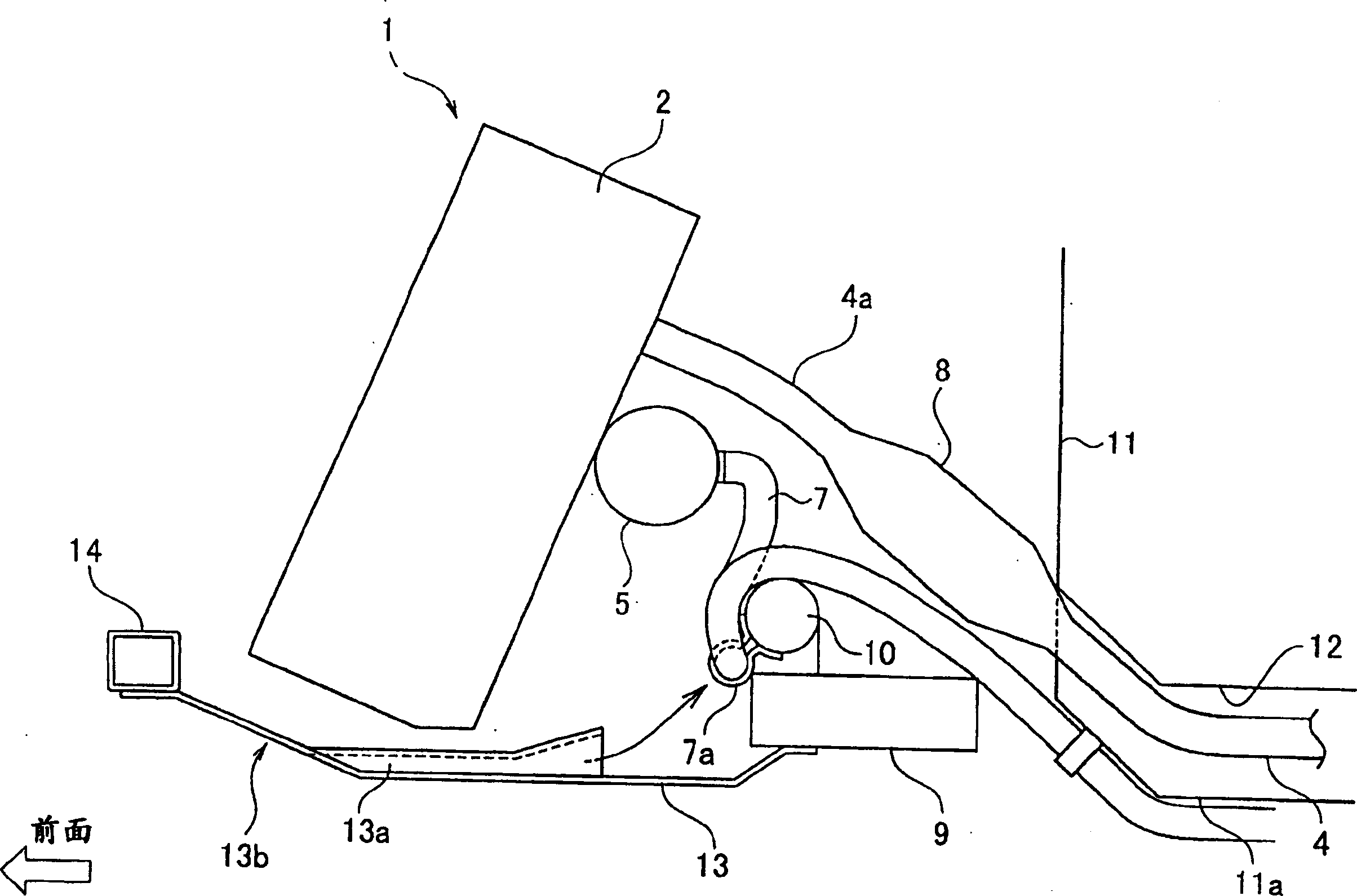
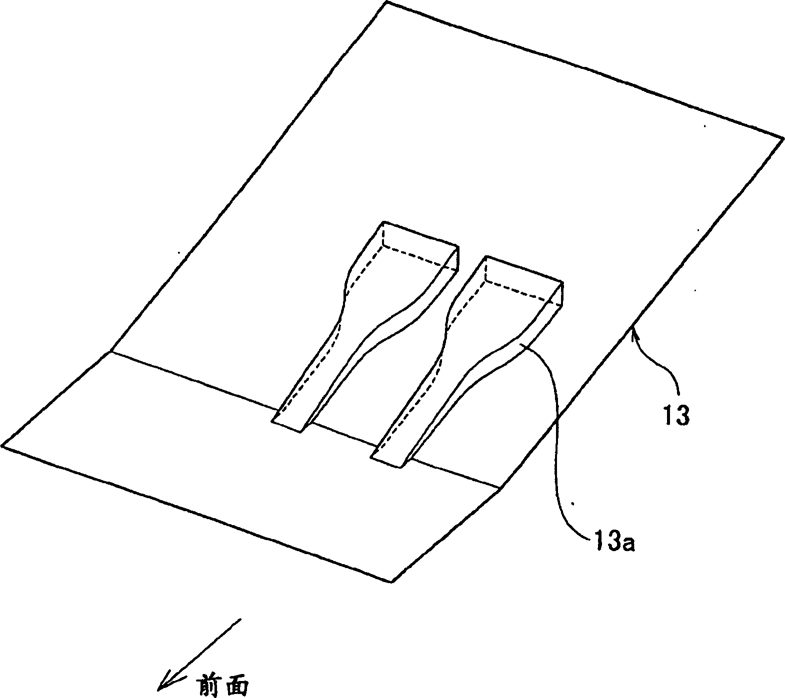
[0015] Figure 1~ image 3 Shown is an embodiment of the wire harness wiring structure of the power cabin of the present invention, and Fig. 1 is a brief structural diagram of the power cabin applying the present invention, figure 2 It is a sectional view cut along the arrow A-A of Fig. 1, image 3 is to zoom in figure 2 A perspective view showing the main parts.

[0016] In Figure 1 and figure 2 Among them, 1 represents the entire powertrain, between a pair of front side parts not shown extending in the front and rear directions of the vehicle body on both sides of the vehicle width direction, through The bracket portion shown in FIG.

[0017] On the engine body 2, an exhaust manifold 4a for exhausting is connected to the rear side, and the exhaust pipe 4 connected to the exhaust manifold 4a through the catalyst 8 passes through the instrument ...


PUM


Abstract

In this harness wiring structure for the engine room, one end of a harness 7 having the other end connected to an electric part 5 provided around an engine body 2 within the engine room where a power unit 1 having an engine body 2 and a transmission 3 is mounted to be transversely installed in a vehicle body front and rear direction is wired toward a rear side of a vehicle body. After fixing the harness 7 to a steering rack unit 10 extended in a vehicle width direction on a lower side of the engine room from a rear side of the engine body 2, the harness 7 is wired from the engine room to the rear side of the vehicle body.

Description

technical field [0001] The present invention relates to an ideal power compartment wiring harness wiring structure applied to a vehicle in which a powertrain including an engine body and a transmission is mounted transversely with respect to the front-rear direction of the vehicle body. Background technique [0002] In recent years, a powertrain consisting of an engine body and a gearbox arranged side by side with the engine body to transmit the driving force of the engine has been mounted on a horizontal support with respect to the front-rear direction of the vehicle body in the power compartment in front of the vehicle body. Vehicles have been added. [0003] Also, in this vehicle, as disclosed in Patent Document 1, the wiring harnesses of electrical components around the engine body are fixed to the side surface of the engine body on the side of the above-mentioned gearbox or to the box of the gearbox with harness clips or the like. On the body, it is arranged on the rea...

Claims


Application Information

Patent Timeline
Patent Type & Authority Patents(China)
IPC IPC(8): B60R16/02B62D65/00B62D25/20B60K13/04B60K17/04
Inventor 桑野泰成
Owner NISSAN MOTOR CO LTD
Features
  • R&D
  • Intellectual Property
  • Life Sciences
  • Materials
  • Tech Scout
  • Unparalleled Data Quality
  • Higher Quality Content
  • 60% Fewer Hallucinations
Learn More