Radio communication device and method

A wireless communication device and a technology for notifying information, which is applied in the field of wireless communication devices and wireless communication, and can solve problems such as complex system structures

Inactive Publication Date: 2000-11-08
PANASONIC CORP
View PDF1 Cites 10 Cited by
  • Summary
  • Abstract
  • Description
  • Claims
  • Application Information

AI Technical Summary

Problems solved by technology

[0009] However, in this method, it is necessary to estimate the symbol rate and the number of modulation values, to estimate the transmission path condition with higher accuracy, and to estimate the modulation method, which will have a complicated system structure.

Method used


Image

  • Radio communication device and method
  • Radio communication device and method
  • Radio communication device and method

Examples


Embodiment 1

[0024] image 3 It is a structural block diagram of the wireless communication device of the present invention. A signal transmitted from a communication partner is received by a receiving unit 102 via an antenna 101 . In the receiving unit 102 , the signal is subjected to various processes of frequency conversion, amplification, and AD conversion, and the processed signal is sent to the demodulation unit 103 . In the demodulation unit 103, predetermined demodulation processing is performed on the signal to obtain received data.

[0025] In addition, the output of the receiving unit 102 and / or the output of the demodulation unit 103 is sent to the channel degradation detection unit 104 , and the state of the channel is determined in the channel degradation detection unit 104 . The determination result is sent to the transmission control unit 106 .

[0026] In addition, the transmission data is sent to the modulation unit 105 , where predetermined modulation processing is pe...

Embodiment 2

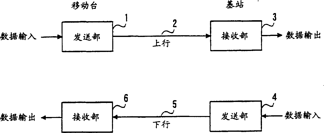
[0043] Figure 7 It is a block diagram showing a schematic configuration of a wireless communication system including a wireless communication device according to Embodiment 2 of the present invention. exist Figure 7 In the wireless communication system shown, data input by a user at a mobile station is sent from a data transmission unit 301 and received by a data reception unit 303 of a base station through an uplink channel 302 . At the same time, the poor channel detection unit 304 of the base station monitors the line state of the uplink channel, and sends feedback signals indicating transmission path deterioration or fading detection parameters to the data sending unit 305 as line state notification information.

[0044] On the other hand, the data transmission unit 305 of the base station transmits the feedback signal including the information data input from the base station and the channel state notification information of the uplink channel through the downlink chan...


PUM


Abstract

Line condition notifying information of a down channel 206)is transmitted as a feedback signal to the destination station while permitting a lowered transmission efficiency of an up channel 202. While the radio line condition of the down channel 206 is poor, the destination station temporarily delays data transmission on receiving the line condition notifying information, thereby preventing unnecessary retransmission and easing channel contention. Data transmission is resumed when the line condition of the transmission line 206 returns to normal.

Description

technical field [0001] The present invention relates to a wireless communication device and a wireless communication method, in particular to a wireless communication device and a wireless communication method suitable for high-speed multimedia communication. Background technique [0002] Conventional systems in wireless communication systems are mainly used to accommodate symmetric traffic, and include FDD (Frequency Division Duplex) and TDD (Time Division Duplex). [0003] figure 1 It is a schematic diagram of the system configuration of the conventional system. A mobile station and a base station, which are communication terminals, each include an independent transmitting and receiving device. The information data input from the base station is sent out by the data sending unit 4 of the base station using the downlink channel 5 . This information data is received by the data receiving unit 6 of the mobile station and transmitted to the data receiving terminal. [0004...

Claims


Application Information

Patent Timeline
Patent Type & Authority Applications(China)
IPC IPC(8): H04L1/00H04L1/18H04W28/04H04W28/22
CPCH04W28/22H04L1/0027H04L1/0001H04L1/0026H04L1/1867H04W28/04
Inventor 石贵增加藤修上杉充
Owner PANASONIC CORP
Why Eureka
Try Eureka