Mechanical fuel gasification apparatus

A technology for fuel and internal combustion engines, which is used in fuel heat treatment devices, fuel re-atomization/homogenization, mechanical equipment, etc., to achieve the effect of improving emission rates

Inactive Publication Date: 2006-09-13
R·W·哈蒙德
View PDF3 Cites 0 Cited by
  • Summary
  • Abstract
  • Description
  • Claims
  • Application Information

AI Technical Summary

Problems solved by technology

These existing methods and devices require complex valving, supply and delivery of water or waste gas

Method used


Image

  • Mechanical fuel gasification apparatus
  • Mechanical fuel gasification apparatus
  • Mechanical fuel gasification apparatus

Examples


example 1

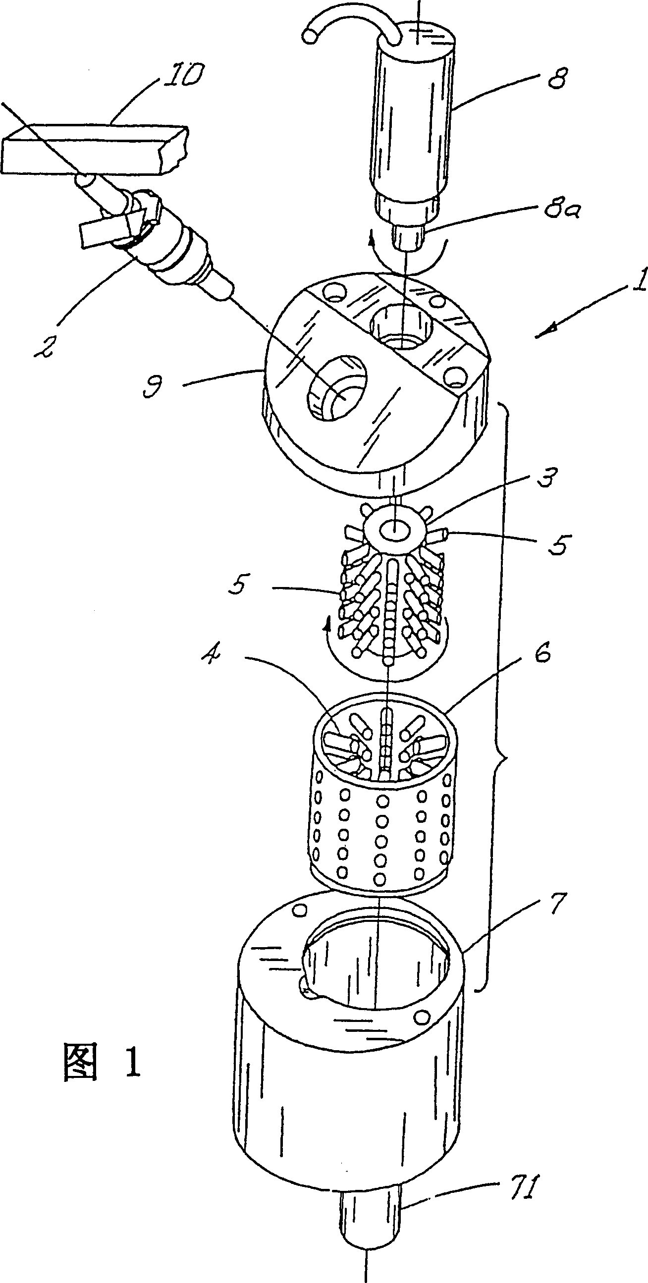
[0044] In a test of the first preferred embodiment, a 1992 Honda Accord fuel injected internal combustion engine with four cylinders was equipped with four gasification devices of the embodiment shown in FIG. 1 . These devices are located between each cylinder's fuel injector and intake manifold. Before installing the gasifier, a 12-mile gas mileage test showed a gas consumption rate of 25 mpg. Repeat testing under the same conditions at the same speed with the gasification device of the present invention installed showed an improvement in gas mileage to 35 mpg. And as the acceleration performance of the internal combustion engine on the car is significantly improved, the performance of the internal combustion engine is also significantly improved.

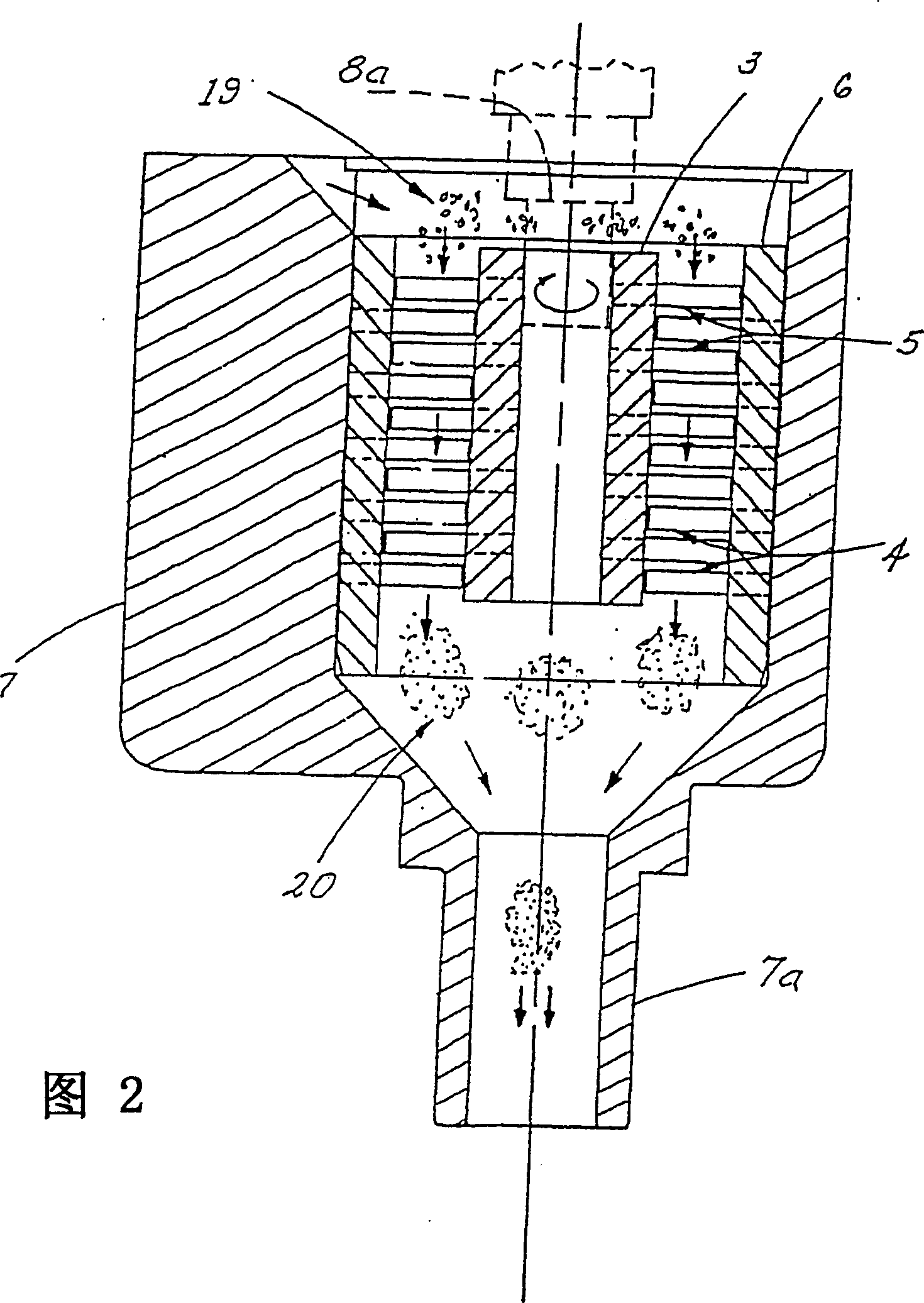
[0045] In another embodiment of the invention, the gasification device is divided into several stages, the diameter of the rotor, stator and chamber in the first stage being smaller than the diameter of the corresponding parts in...


PUM


Abstract

A method and apparatus (1) for mechanically gasifying an atomized fuel / air mixture by passing the mixture through intermeshing sets of pins (4, 5) rotating at high speeds. When used in an internal combustion engine, the fuel efficiency is enhanced and undesirable emissions are reduced.

Description

technical field [0001] The present invention relates to a method and apparatus for the mechanical vaporization of most liquid fuels for internal combustion engines, thereby increasing fuel mileage and power and reducing pollutant emissions. Background technique [0002] It has long been recognized in the design of internal combustion engines that achieving an optimal fuel / air mixture ratio is a major factor in improving efficiency. The fuel is then burned as completely as possible. Obviously, the complete combustion of fuel can produce the most energy per unit mass of fuel while reducing the proportion of unburned or partially burned fuel in the exhaust gas of the internal combustion engine, and most of the pollutants come from the above-mentioned unburned or partially burned fuel . [0003] In the past, carburetors and fuel injectors typically provided a fuel / air mixture in the form of a mist or vapor. These mixtures have very small fuel droplets suspended in the air lik...

Claims


Application Information

Patent Timeline
Patent Type & Authority Patents(China)
IPC IPC(8): F02M31/00F02M29/02
CPCF02M29/02
Inventor R·W·哈蒙德
Owner R·W·哈蒙德
Why Eureka
Try Eureka