
Array antenna transceiver and calibrating method of transmission route used for same

An array antenna and transceiver technology, applied in the field of calibration of phase/amplitude characteristics, can solve problems such as complex signal processing, increased signal processing load, and increased number of routes

Inactive Publication Date: 2006-11-01
NEC CORP
View PDF1 Cites 0 Cited by
  • Summary
  • Abstract
  • Description
  • Claims
  • Application Information

AI Technical Summary

Problems solved by technology

Therefore, when a conventional calibration method is applied to a transceiver that performs broadband transmission through individual antenna elements by using hundreds to thousands of subcarriers, a problem arises that greatly increases the scale of the transceiver
[0032] Third, the number of routes to be calibrated is greatly increased, and signal processing becomes complex even with time-division calibration every several subcarriers
Therefore, when a conventional calibration method is applied to a transceiver that performs broadband transmission through individual antenna elements by using hundreds to thousands of subcarriers, a problem arises that greatly increases the signal processing load in calibration

Method used


Image

  • Array antenna transceiver and calibrating method of transmission route used for same
  • Array antenna transceiver and calibrating method of transmission route used for same
  • Array antenna transceiver and calibrating method of transmission route used for same

Examples


Embodiment Construction

[0052] Next, embodiments of the present invention will be described in detail below with reference to the drawings.

[0053] [1] Structure description

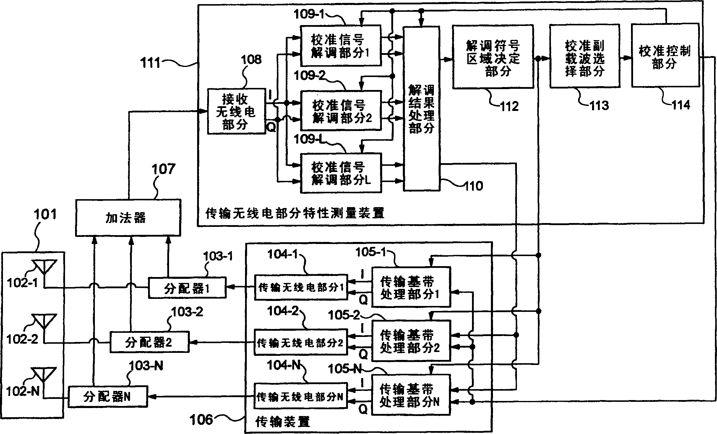
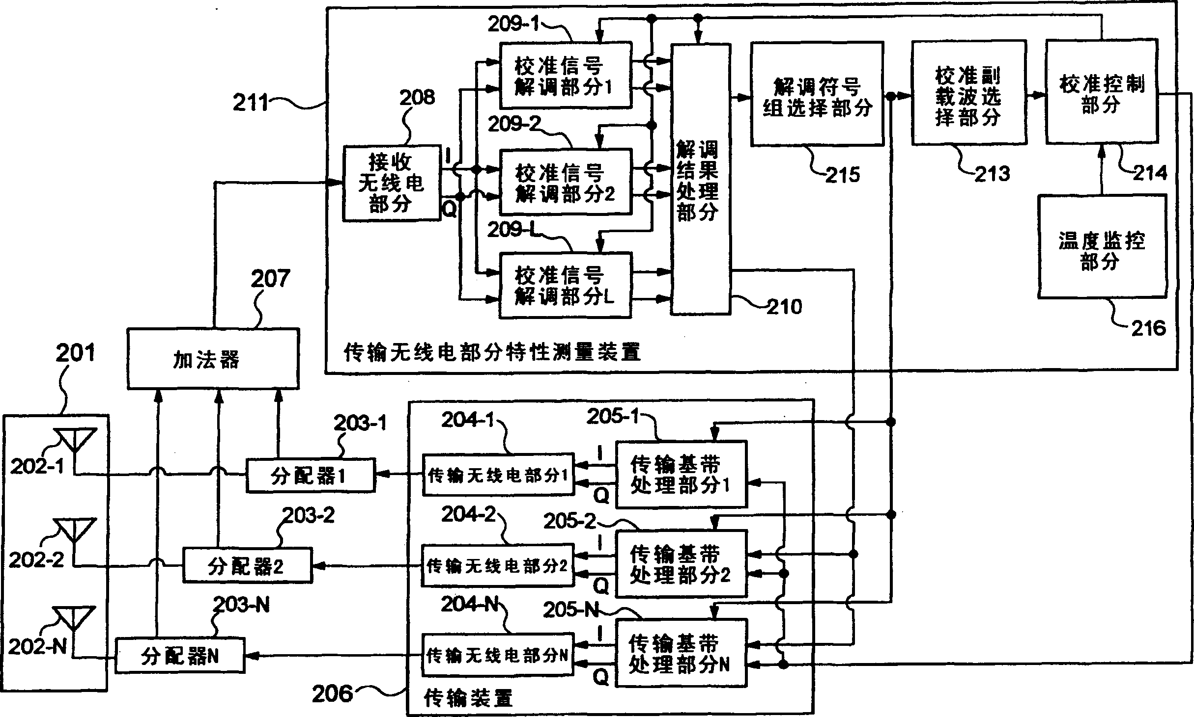
[0054] figure 1 is a block diagram showing the structure of the first embodiment of the present invention.

[0055] The array antenna (101) is composed of N antenna elements (102-1 to 102-N) arranged closely so that the correlation between the antennas becomes high.

[0056] The distributor (103-1) to the distributor (103-N) receive the output of the transmission radio part 1 (104-1) to the transmission radio part N (104-N), and the output thereof on the one hand and the antenna element (102- 1 to 102-N) and the output on the other hand is connected to an adder (107).

[0057] The adder (107) receives the user communication signal and the calibration signal from the distributor (103-1) to the distributor (103-N), combines these signals in the radio frequency band, and outputs the combined signal to the receiving radio sect...


PUM


Abstract

The present invention provides a calibration method for an array antenna transceiver that performs multi-carrier transmission, which can minimize the growth of the transceiver scale and signal processing load and maintain a certain calibration accuracy. The method includes the following parts: a demodulation symbol area determining device for classifying and grouping, for each area, demodulation symbol points (phase / amplitude information) of calibration signals transmitted from all subcarriers in all transmission routes; calibration Subcarrier selection means for selecting a demodulation symbol as a typical value from the demodulation symbol group grouped for each area and its transmission route number and subcarrier number; calibration control means for sending a calibration signal for transmission a transmission route, a subcarrier and a demodulated transmission route and a subcarrier; a calibration signal demodulation device for demodulating the calibration signal according to the information on the transmitted transmission route and subcarrier; and a transmission baseband processing device for Calibration signals are generated for all subcarriers and calibration coefficients are set based on the transmitted transmission route and information on the subcarriers.

Description

technical field [0001] The present invention relates to a communication device for broadband transmission by using tens to hundreds or more sub-carriers, in particular to an array antenna transceiver for adaptive antenna control, more particularly to an array antenna transceiver Calibration of phase / amplitude characteristics between antennas. Background technique [0002] For cellular mobile communication systems, a method is studied, which forms a transmission directivity pattern by using an array antenna transceiver composed of highly correlated multiple antenna elements to improve signal speed and quality, increase User capacity, and increase transmission gain and reduce interference to other users in the incoming direction of the desired signal. In this case, the array antenna transceiver forms a directional pattern of the transmitted signal towards the incoming direction obtained from the desired signal received from the array antenna. [0003] In the case of array an...

Claims


Application Information

Patent Timeline
Patent Type & Authority Patents(China)
IPC IPC(8): H04Q7/20H01Q21/00H04B14/08H01Q3/26H04B7/10H04J1/20H04L27/00H04L27/18H04L27/26H04L27/38
CPCH04B7/0613H04B17/12H04B17/21
Inventor 东友洋
Owner NEC CORP
Learn More