Convergent deflection yoke

A technology of deflection coils and coils, which is applied in the direction of cathode ray tubes/electron beam tubes, electrode devices and related components, contacts, etc. It can solve the problem of coil performance determination, cannot obtain winding distribution exclusively, and cannot grasp coil performance, etc. problem, achieve the effect of improving focusing performance and suppressing deformation

Inactive Publication Date: 2006-11-08
SANYO ELECTRIC CO LTD +1
View PDF0 Cites 0 Cited by
  • Summary
  • Abstract
  • Description
  • Claims
  • Application Information

AI Technical Summary

Problems solved by technology

[0009] Furthermore, even if the Ak coefficient ratio A3 / A1 is in the range of 0.13 to 0.50, the magnetic field intensity distribution will change greatly in this range. When designing the convergence deflection coil, if it is not actually measured And the resulting deformation, it is impossible to grasp the performance of its coil
The reason for this can be considered that, as shown in Fig. 25, the current density distribution expressed by the sum of the two terms A1 and A3 of the Fourier series deviates greatly from the actual current density distribution, and therefore, the performance of the coil cannot be It is determined only by the ratio of Ak coefficient A3 / A1
[0010] As mentioned above, the conventional technology has the problem of not being able to exclusively obtain the winding distribution that can make the magnetic field strength more uniform.

Method used


Image

  • Convergent deflection yoke
  • Convergent deflection yoke
  • Convergent deflection yoke

Examples


Embodiment Construction

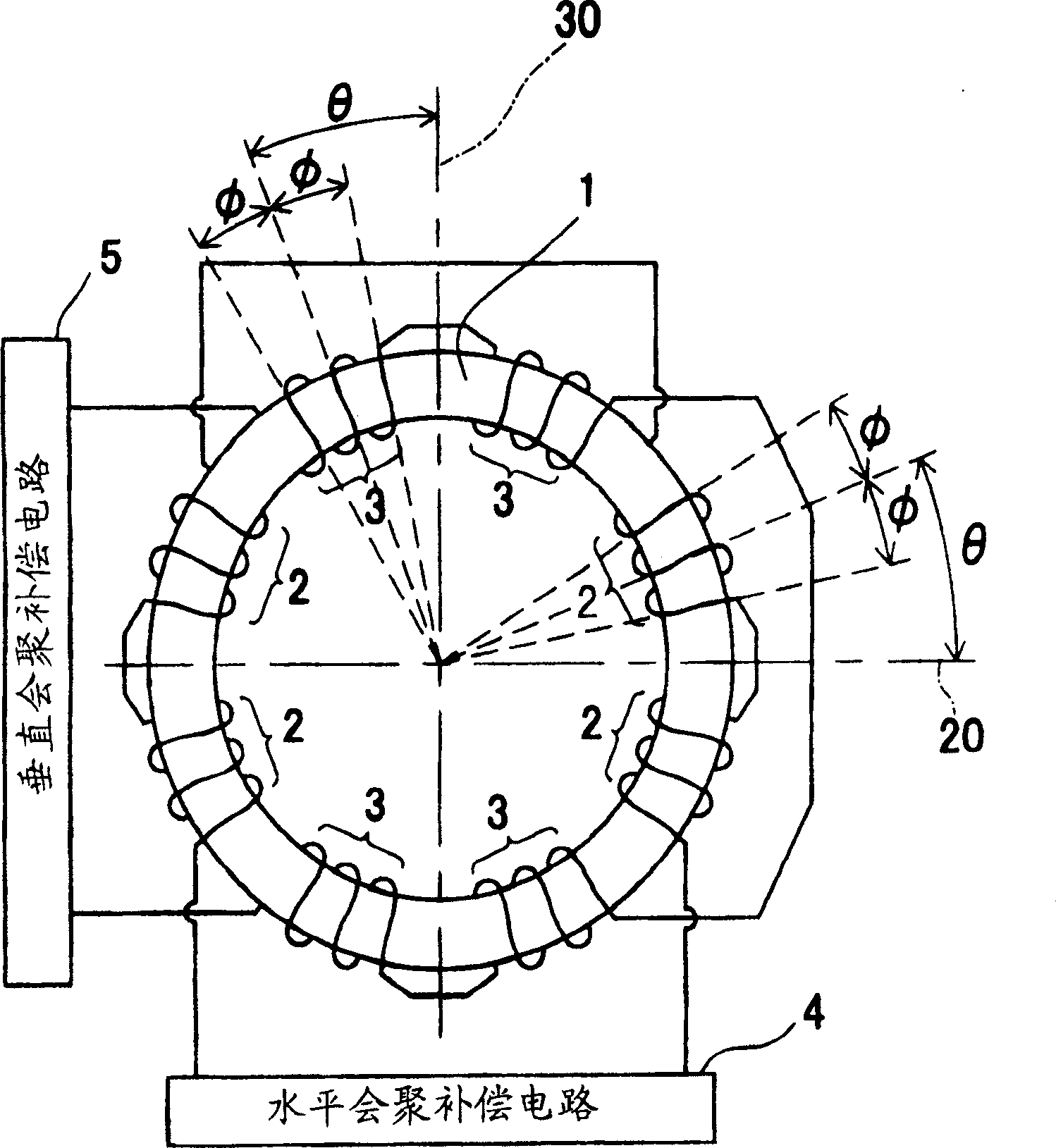
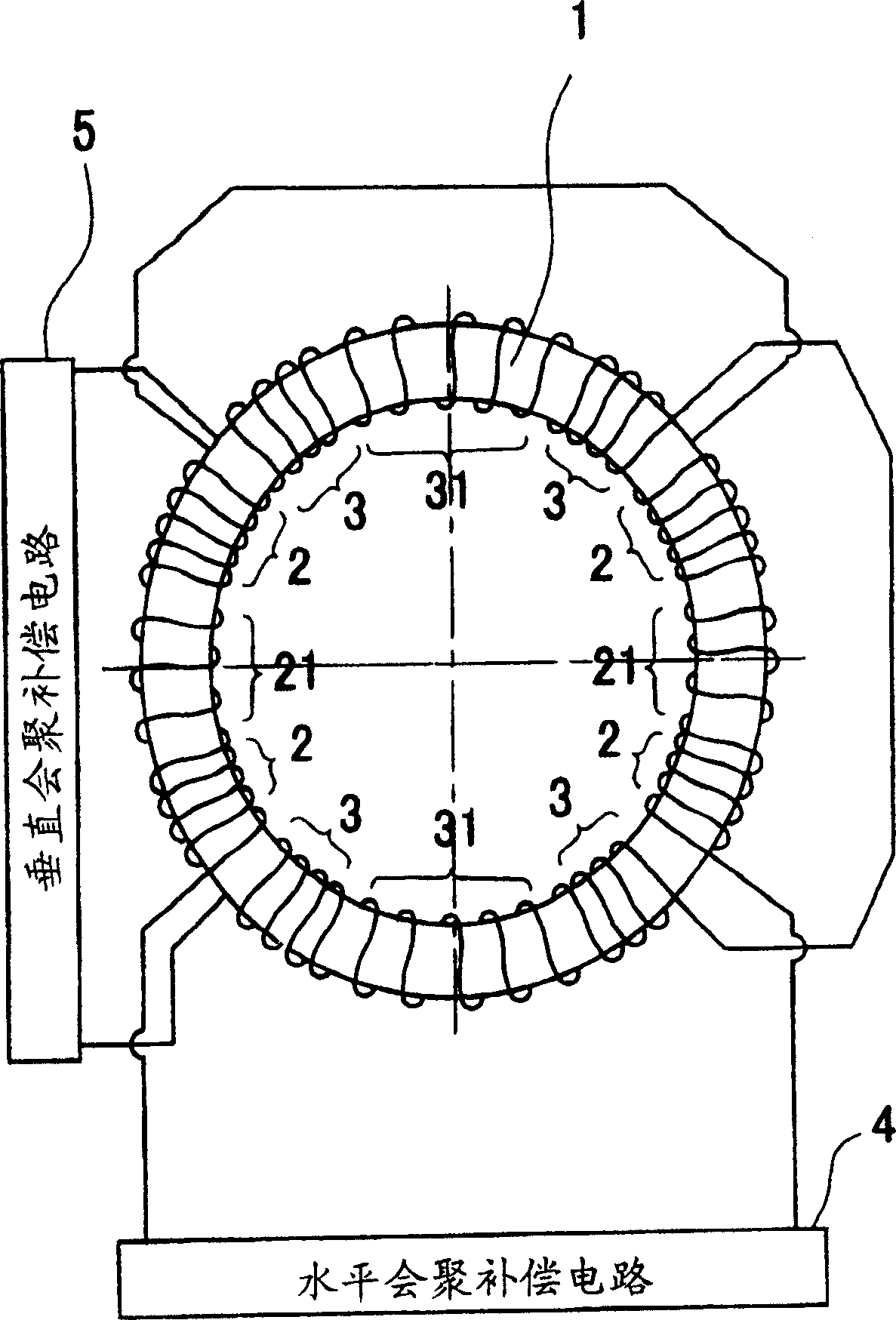
[0043] Hereinafter, the embodiments of the present invention will be described in detail with reference to the accompanying drawings. Convergence deflection coils involved in the present invention are as figure 1 As shown, it is formed by winding a horizontal coil 2 and a vertical coil 3 on an annular core 1 , the horizontal coil 2 is connected with a horizontal convergence compensation circuit 4 , and the vertical coil 3 is connected with a vertical convergence compensation circuit 5 . The coil winding density distribution and cos 2 θ is proportional.

[0044] Image 6 Shown is the result of the magnetic field strength distribution calculated by the present inventors through computer simulation for a converging deflection yoke in which a horizontal coil is wound with the above-mentioned winding density distribution over the entire circumference of the toroidal core. As shown in the figure, the magnetic field intensity distribution is in the shape of concentric circles, and...


PUM


Abstract

The converging deflection coil involved in the present invention is used to generate a 2-pole magnetic field intended to deflect the electron beam in the horizontal or vertical direction, and is formed by winding a horizontal coil (2) and a vertical coil (3) on an annular core (1) The horizontal coil (2) and the vertical coil (3) are wound on the annular core (1) with the horizontal coil reference axis (20) and the vertical coil reference axis (30) perpendicular to each other as the reference, and it is characterized in that the horizontal coil ( 2) has a winding density distribution with the winding angle (θ) from the horizontal coil reference axis (20) of the toroidal core (1) as a variable, and the vertical coil (3) has a vertical winding angle (θ) from the toroidal core (1) The winding density distribution with the winding angle (θ) from the coil reference axis (30) as a variable, the winding density distribution of each coil (2, 3) and cos 2 θ is proportional. This results in a more uniform distribution of the magnetic field strength than in the prior art.

Description

technical field [0001] The present invention relates to a convergence deflection coil for generating a 2-pole magnetic field for deflecting electron beams in a horizontal direction or a vertical direction, mounted on a cathode ray tube of a projection TV set or the like. Background technique [0002] Convergence deflection coils such as figure 1 As shown, it is formed by winding a horizontal coil 2 and a vertical coil 3 on an annular core 1 , the horizontal coil 2 is connected with a horizontal convergence compensation circuit 4 , and the vertical coil 3 is connected with a vertical convergence compensation circuit 5 . In such a convergence deflection yoke, in order to suppress the deformation of the electron beam along with the deflection and improve the focusing performance, it is necessary to form a uniform magnetic field in the electron beam passing area. [0003] For this reason, such a scheme is proposed in the document "SENIMAR M-4 1991 SID "Deflection And Convergenc...

Claims


Application Information

Patent Timeline
Patent Type & Authority Patents(China)
IPC IPC(8): H04N9/28H01J29/76H01F7/00H01H1/00H01J29/70
CPCH01J29/705H01J29/764H01J2229/7033H04N9/28
Inventor 宫崎雅彦
Owner SANYO ELECTRIC CO LTD
Why Eureka
Try Eureka