Bistable four-way electromagnetic reversing valve

An electromagnetic reversing valve and bistable technology, which is applied to multi-way valves, valve details, valve devices, etc., can solve the problems of complex structure, poor reversing reliability, and low action sensitivity of four-way electromagnetic reversing valves. Achieve the effects of convenient manufacturing and assembly, reduced cost, and high action sensitivity

Inactive Publication Date: 2007-01-03
ZHEJIANG SANHUA INTELLIGENT CONTROLS CO LTD
View PDF6 Cites 0 Cited by
  • Summary
  • Abstract
  • Description
  • Claims
  • Application Information

AI Technical Summary

Problems solved by technology

[0002] In the prior art, electromagnetic reversing valves for refrigeration include two-position three-way electromagnetic valves, four-way electromagnetic reversing valves, etc., which are dedicated to reversing the flow of refrigerant in refrigeration systems, such as heating and cooling air conditioners, etc. According to the principle of refrigeration, the change of the flow direction of the refrigerant will cause the change of the cooling or heating effect, so in fact the function of the reversing valve and the effect of reversing will affect the cooling effect of the refrigeration system after using the above electromagnetic reversing valve
But at present, the overall structure of the four-way electromagnetic reversing valve is relatively complicated. The internal structure includes a valve body, at least one associated valve cavity, a valve core, and an electromagnetic coil are installed in the valve cavity.
The four-way electromagnetic reversing valve with this structure still has the disadvantages of low action sensitivity, poor reversing reliability, high cost, and no power-off memory function.

Method used


Image

  • Bistable four-way electromagnetic reversing valve
  • Bistable four-way electromagnetic reversing valve
  • Bistable four-way electromagnetic reversing valve

Examples


Embodiment Construction

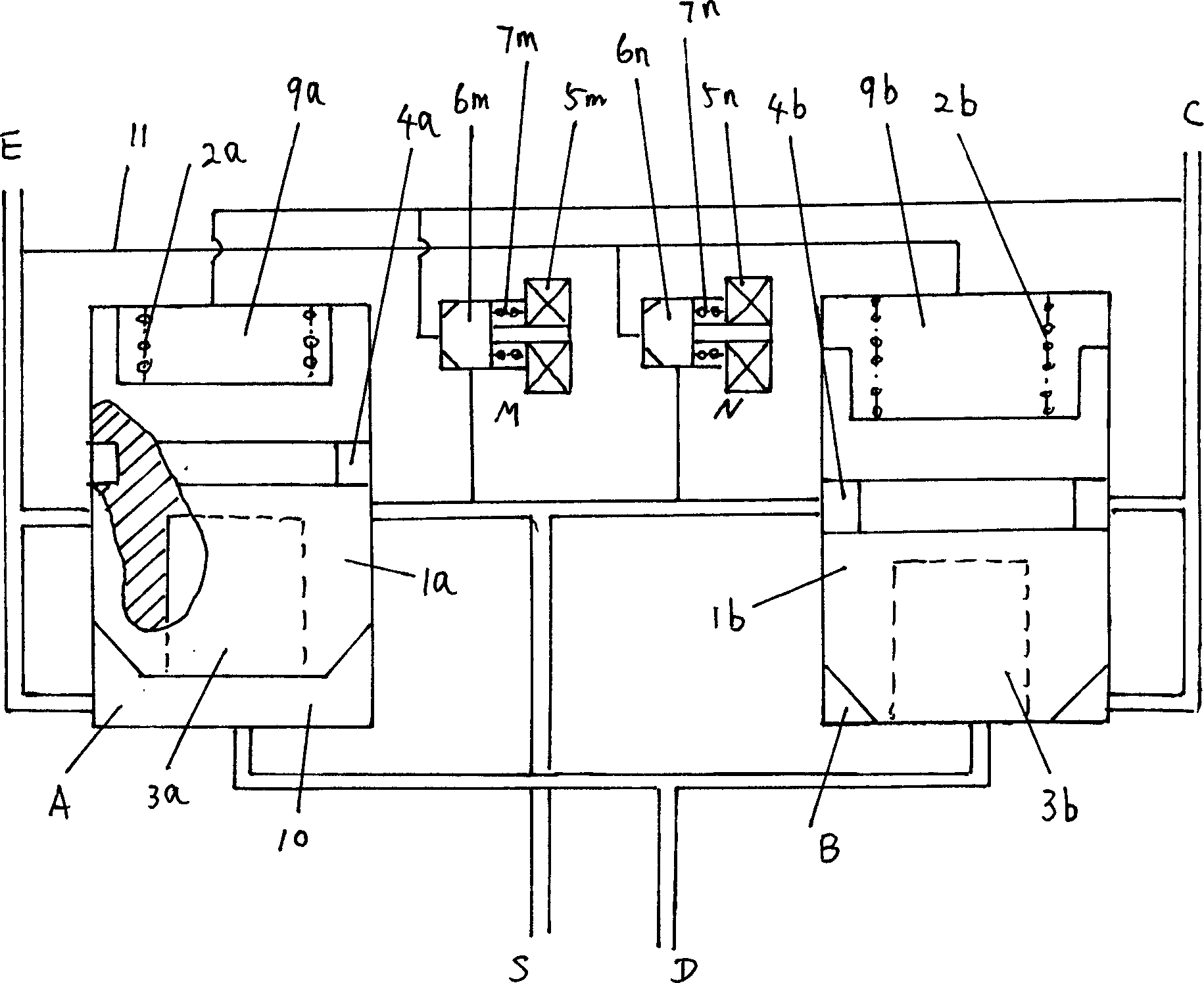
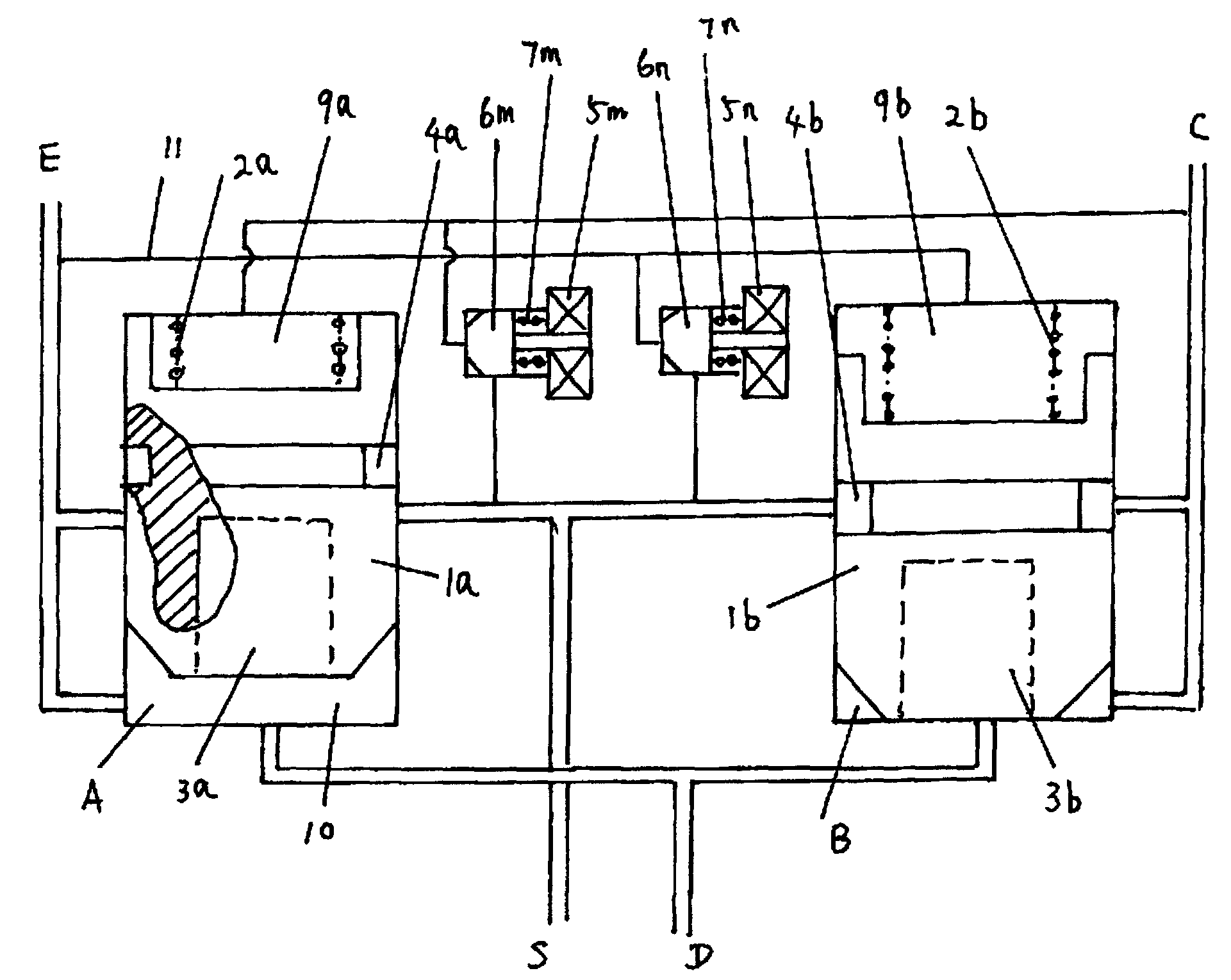
[0011] The present invention will be described in detail below in conjunction with accompanying drawing: figure 1 As shown, the present invention has two valve chambers A and B respectively equipped with spool valve cores 1a and 1b. The front ends of the spool valve cores 1a and 1b are in the shape of a cone, and the distance between their tail ends and the bottom surface of the valve chamber is uniform. Respective springs 2a and 2b are respectively placed. Under normal circumstances, the spools 1a and 1b are respectively at the bottom of the respective valve chambers A and B under the action of the return springs. Cavities 3a, 3b are respectively opened on the front end surfaces of the spool valve cores 1a and 1b, and their arrangement can save material, and they can also make the front ends of the spool valve cores slightly deform to enhance the sealing effect. The spool valve cores 1a and 1b are made of materials such as graphite, rubber, etc., which are resistant to high t...


PUM


Abstract

The bistable four-way electromagnetic reversal valve includes two valve cavities, their interior is respectively equipped with slide valve core, the middes and front ends of two valve cavities are communicated and respectively connected with pipes of E, C, S and D. Besides, it also includes two control valve cavities with poppet, the middles of two control valve cavirites are simultaneously communicated with pipe S, and frnot ends of two control valve cavities are respectively connected with pipe E or pipe C.

Description

technical field [0001] The invention relates to a valve for controlling fluid flow, in particular to a four-way reversing valve which is suitable for fluid switching in a heat pump air-conditioning system and is electromagnetically controlled, belonging to the category of valves. Background technique [0002] In the prior art, electromagnetic reversing valves for refrigeration include two-position three-way electromagnetic valves, four-way electromagnetic reversing valves, etc., which are dedicated to reversing the flow of refrigerant in refrigeration systems, such as heating and cooling air conditioners, etc. According to the principle of refrigeration, the change of the flow direction of the refrigerant will cause the change of the cooling or heating effect, so in fact the function of the reversing valve and the effect of reversing will affect the cooling effect of the refrigeration system after using the above electromagnetic reversing valve. But at present, the overall s...

Claims


Application Information

Patent Timeline
Patent Type & Authority Patents(China)
IPC IPC(8): F16K11/20F16K31/06
Inventor 贾正余
Owner ZHEJIANG SANHUA INTELLIGENT CONTROLS CO LTD
Why Eureka
Try Eureka