
Electronic equipment cooling member

A technology for cooling components and electronic equipment, which is applied in the construction parts of electrical equipment, electrical components, cooling/ventilation/heating transformation, etc., which can solve the problems of increased product costs and electronic equipment not suitable for use as household appliances, etc.

Inactive Publication Date: 2007-01-17
PANASONIC CORP
View PDF3 Cites 0 Cited by
  • Summary
  • Abstract
  • Description
  • Claims
  • Application Information

AI Technical Summary

Problems solved by technology

Thereby, make its product cost increase, so, the electronic equipment that has such heat exchanging device is unsuitable as household appliance

Method used


Image

  • Electronic equipment cooling member
  • Electronic equipment cooling member
  • Electronic equipment cooling member

Examples


Embodiment 1

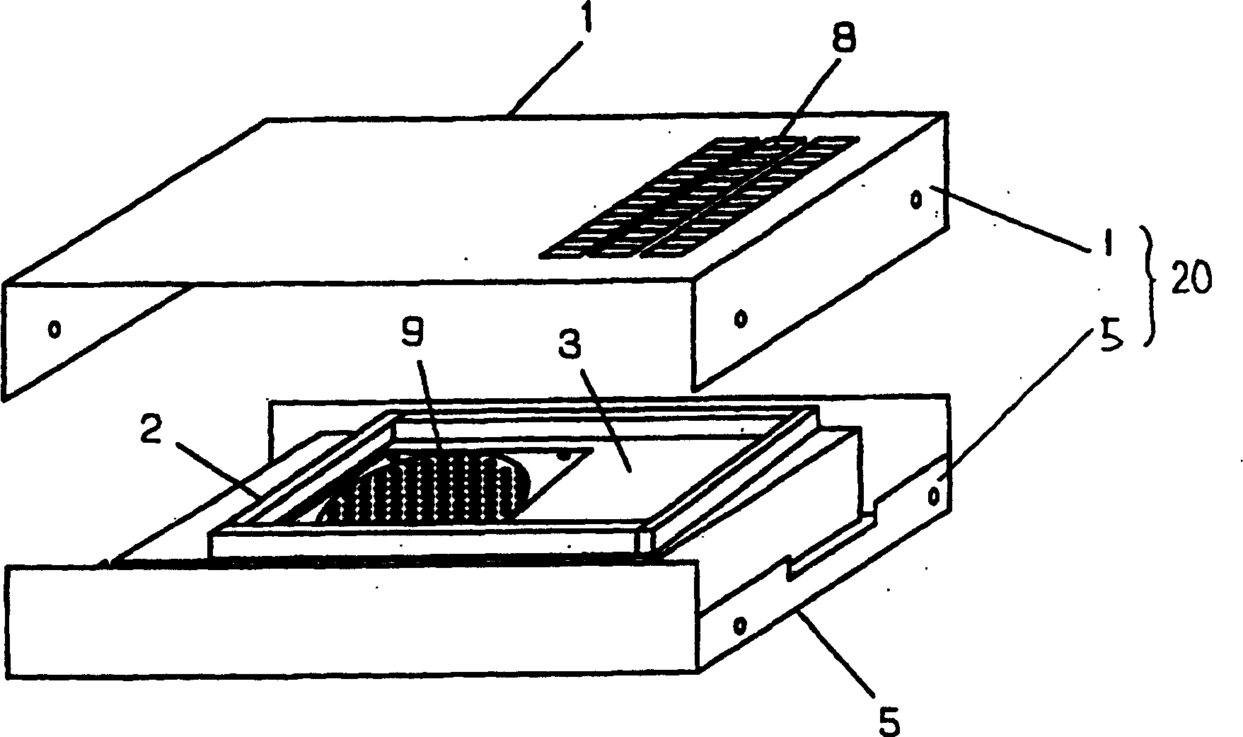
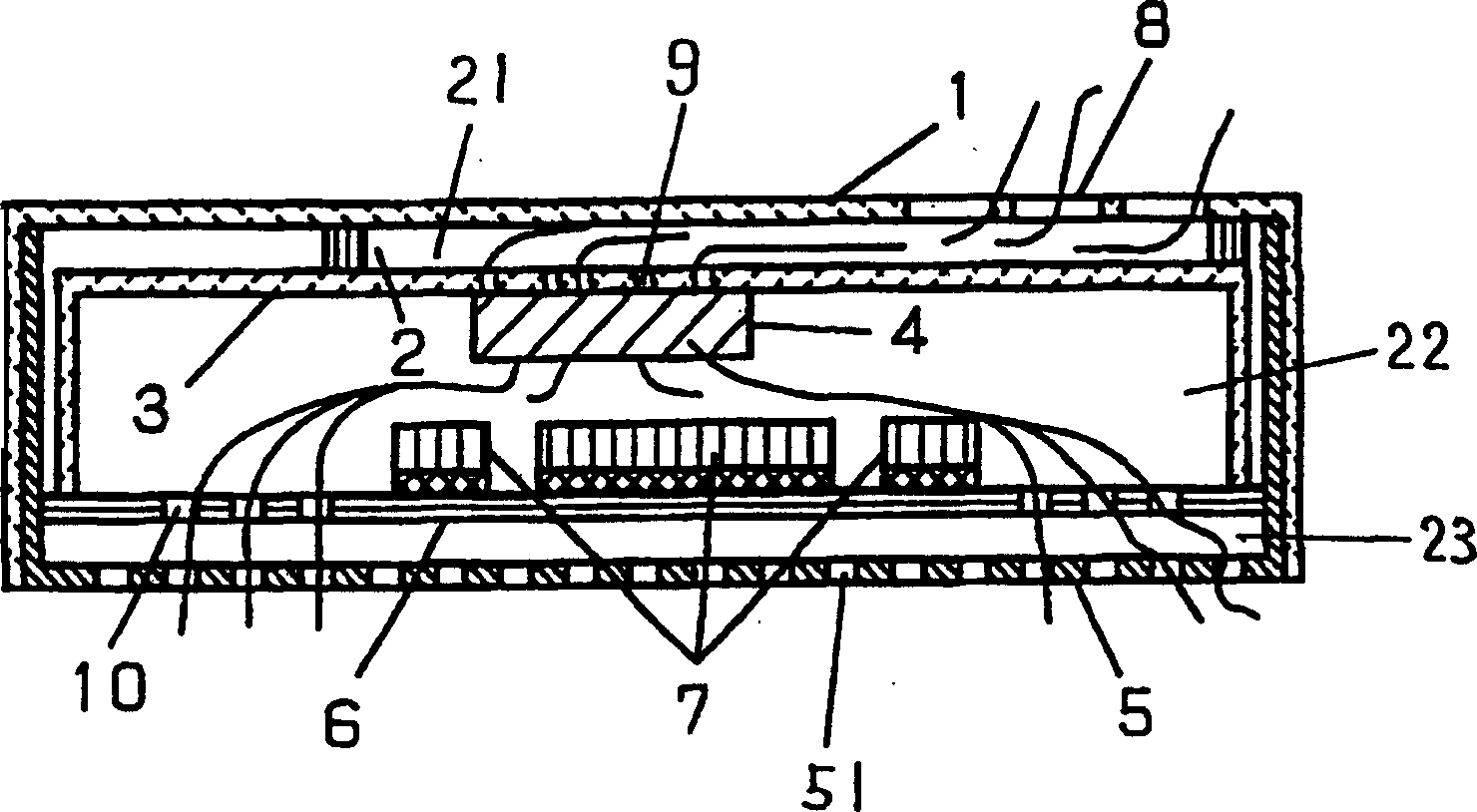
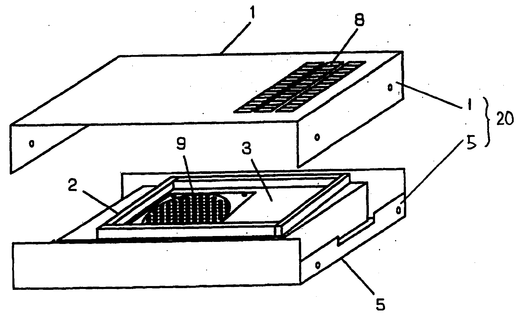
[0035] figure 1 Shown is an exploded perspective view of an electronic equipment cooling member in an exemplary embodiment of the present invention. figure 2 shown from figure 1 A cross-sectional view viewed from the side.

[0036] exist figure 1 and figure 2 Among them, the cooling components of the electronic equipment include: a box structure 20 , a circuit board 6 , a shielding box 3 , a fan 4 and a frame 2 for a wind tunnel. The box structure 20 includes a bottomed container-shaped base 5 and a top plate 1 covering the base 5 . The shielding box 3 covers the circuit substrate 6 and is disposed on the circuit substrate 6 . The fan 4 has the function of discharging the air in the box structure 20 to the outside of the box structure 20 . The circuit board 6 has a heat generating component 7 . The first cooling holes 8 are formed on the top plate 1 . The first ventilation hole 9 is formed on the shielding box 3 . The second vent hole 10 is formed on the circuit sub...


PUM


Abstract

Accumulation of heat in the electronic appliance is prevented, and the electronic appliance is cooled efficiently. Not requiring extra molded part as duct, the cost is saved. The noise level is lowered. This is a cooling structure for an electronic appliance having heat generating parts (7). The cooling structure includes a housing (20) having a top panel (1), side panels, and a bottom panel (5), a case (3) disposed in the housing, a circuit board (6) disposed in the case, and a frame (2) disposed in the space between the top panel and case. The circuit board has the heat generating parts. The space enclosed by the top panel, case and frame forms a wind tunnel (21). The heat generated in the heat generating parts is exhausted outside of the housing by the air passing through the wind tunnel. The case and the circuit board have the circuit board disposed in the housing, and a shield case (3) disposed to cover the circuit board.

Description

technical field [0001] The invention relates to an electronic equipment cooling component. Background technique [0002] Conventionally, electronic devices such as printed circuit boards on which various electronic components are mounted or accommodate circuit boards are cooled by heat exchange devices such as exhaust fans and heat pipes mounted on equipment boxes. Alternatively, natural convection is used to dissipate heat to the outside, thereby cooling box-shaped electronic equipment. [0003] However, when the fan is directly installed on the box body, the noise emitted by the box structure of the electronic equipment increases due to the rotation noise of the fan and the high-speed blowing sound. Therefore, if such a fan is installed in an electronic device commonly used in a home, noise will be generated. Therefore, the above-mentioned electronic equipment with a fan is not suitable for use as household electronic equipment. On the other hand, if the fan is housed i...

Claims


Application Information

Patent Timeline
IPC IPC(8): H05K7/20H05K9/00
CPCH05K7/20127H05K9/0041H05K7/20136
Inventor 前原健一
Owner PANASONIC CORP
Learn More