Method for controlling the speed of a thread feeding device in a rapier loom or projecting weaving machine and thread processing system

A speed control, rapier loom technology, used in looms, textiles, papermaking, textiles, etc., can solve the problem of not being used to calculate the amount of yarn, reduce structural equipment, improve work performance, yarn feeding device Simplified effect

Inactive Publication Date: 2007-01-31
IROPA AG (CH)
View PDF3 Cites 0 Cited by
  • Summary
  • Abstract
  • Description
  • Claims
  • Application Information

AI Technical Summary

Problems solved by technology

However, the data transmitted from the master control unit is not used to calculate the amount of yarn supplied

Method used


Image

  • Method for controlling the speed of a thread feeding device in a rapier loom or projecting weaving machine and thread processing system
  • Method for controlling the speed of a thread feeding device in a rapier loom or projecting weaving machine and thread processing system
  • Method for controlling the speed of a thread feeding device in a rapier loom or projecting weaving machine and thread processing system

Examples


Embodiment Construction

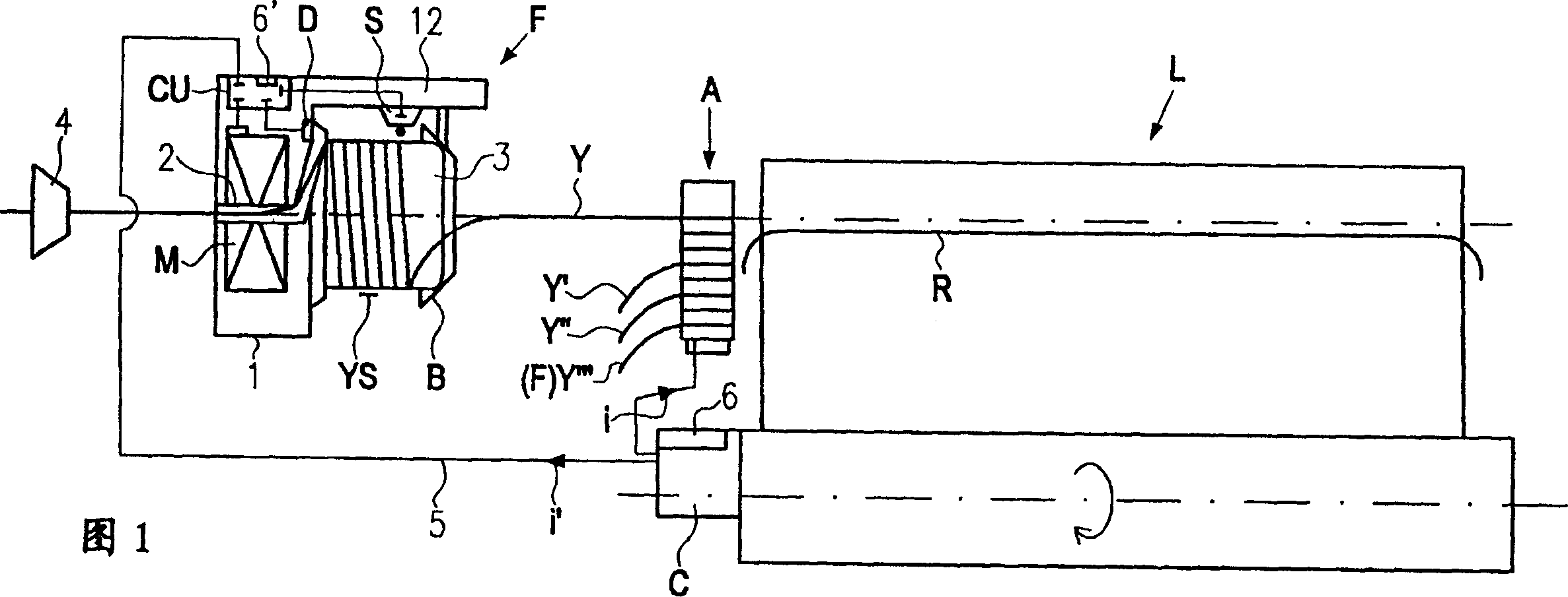
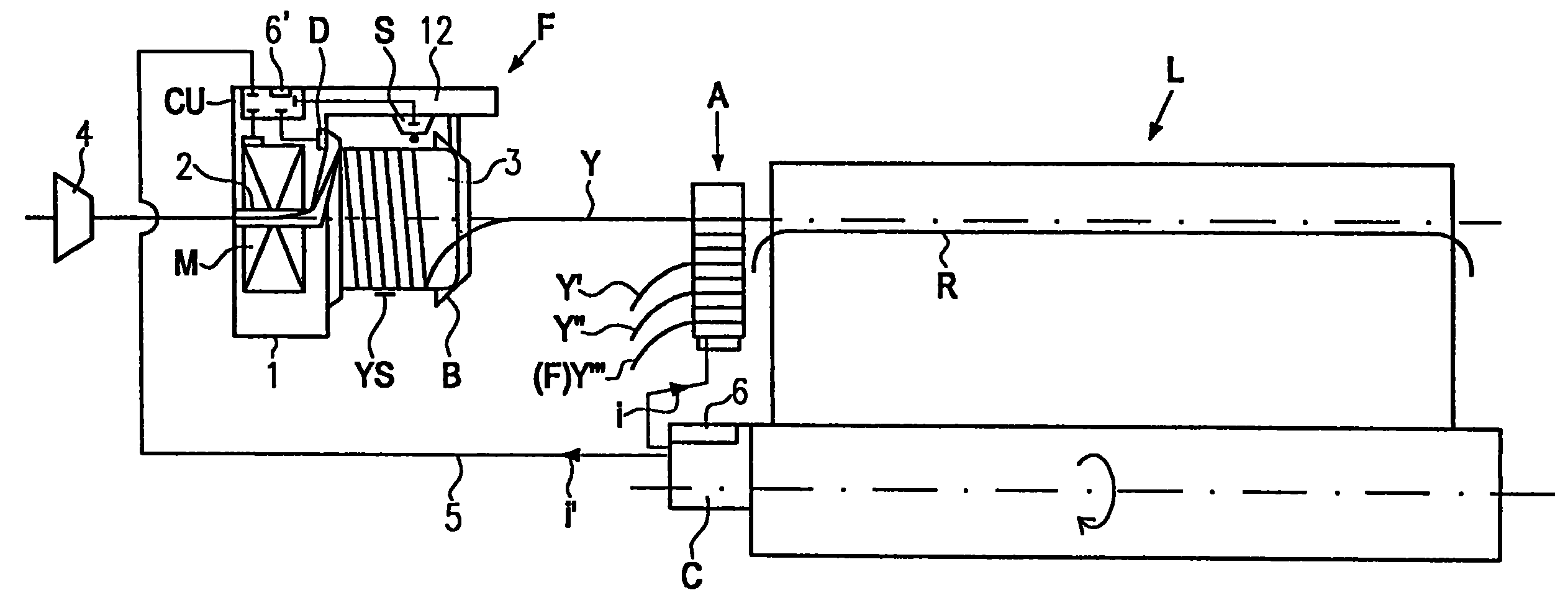
[0026]A yarn processing system S as shown in FIG. 1 comprises a rapier loom or projectile loom L and at least one weft yarn feeding device F. As shown in FIG. Loom L works using several channels. The feeding device F shown feeds yarn along a channel. The weaving machine L comprises: at least one insert element R, for example a rapier or a projectile; a respective channel selection device or color selection device A; and a master control unit C. In the master control unit C, data related to the future working phase of the loom L is obtained, for example, the data is in a programmed form, and for example, the data is related to the weaving pattern. The main control unit C, in particular by means of the information i generated in it in the form of data, controls the channel selection device or the color selection device A respectively, so as to insert only the few weft yarns supplied by the corresponding weft yarn feeding device F of the channel. One of different weft yarns Y, ...


PUM


Abstract

The invention relates to a method for controlling the drive speed of a thread feeding device (F) supplying a channel in a rapier loom or projecting weaving machine (L). According to the inventive device, the data on a future working phase of the weaving machine (L) is transmitted in said channel by the main control unit to the weaving machine to a speed control unit of the thread feeding device (F) in addition to signal data from an individual thread sensor (S) and speed data of the drive motor (M). Said data makes it possible to calculate the amount of thread necessary for the working phase in said channel and the drive speed of the drive motor (M) is deduced from the calculated amount of thread and correspondingly adjusted.

Description

technical field [0001] The present invention relates to a method for controlling the speed at which a weft yarn feeding device feeds weft yarn into the passage of a rapier or projectile loom and to a yarn processing system consisting of a rapier or projectile loom. Background technique [0002] Yarn feeding devices feeding the different channels in rapier or projectile looms are usually used as autonomous units. This means that the speed control unit of the yarn feeding device calculates the amount of yarn required to compensate for the instantaneous consumption by judging the instantaneous driving speed and with the help of several yarn monitoring sensors, and derives and adjusts the driving speed based on the calculated yarn amount, so as to achieve always Provide a sufficient yarn supply for instantaneous consumption. In this case, it is even possible to judge the yarn supply situation in the recent past and up to the instant point at the time of calculation, but it is n...

Claims


Application Information

Patent Timeline
Patent Type & Authority Patents(China)
IPC IPC(8): B65H51/00D03D47/34
CPCD03D47/34
Inventor 拉尔斯·亥尔格·高特弗瑞德·索兰德斯迪格阿尔恩·布洛姆
Owner IROPA AG (CH)
Why Eureka
Try Eureka