Slice level control circuit
A technology for controlling circuit and clipping level, applied in the field of clipping level control circuit, can solve the problem of difficulty in changing the optimal filtering characteristics, etc., and achieve the effect of stability and tracking.
- Summary
- Abstract
- Description
- Claims
- Application Information
AI Technical Summary
Problems solved by technology
Method used
Image

Examples
Embodiment Construction
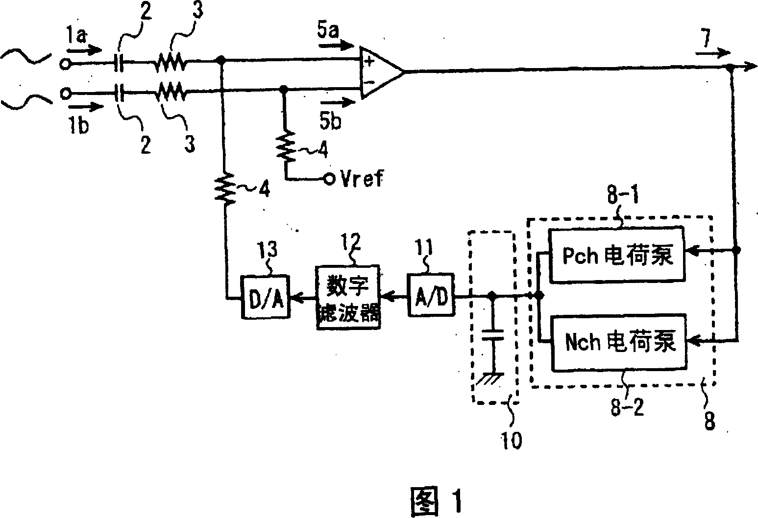
[0020] The slice level control circuit according to the embodiment of the present invention has the configuration shown in FIG. 1 . Hereinafter, description will be given with reference to FIG. 1 . In the slice level control circuit of this embodiment, an analog input signal read from an optical disk is input as a positive phase signal 1a and a reverse phase signal 1b. The so-called positive phase signal 1a and reverse phase signal 1b are analog input signals with the same amplitude but opposite phases. The analog input signal 1b becomes a C-block RF signal 5b that blocks direct current (DC) components and adjusts to a predetermined DC level by connecting capacitor 2, resistor 3, and resistor 4 in series and applying a fixed voltage Vref to one end of resistor 4. On the other hand, the analog input signal 1a also passes through the capacitor 2, the resistor 3, and the resistor 4 connected in series and adjusts the voltage applied to one end of the resistor 4 to become a direc...
PUM
 Abstract
Description
Claims
Application Information