
Hollow type back illumination beam component

A backlight, hollow technology, applied to optical components, light guides of lighting systems, light guides, etc., can solve the problems of reduced luminous flux, short light guide paths, affecting the viewing quality of LCD displays of backlight components, etc., to achieve high brightness output, reduce effect of influence

Inactive Publication Date: 2007-03-28
BENQ CORP
View PDF4 Cites 0 Cited by
  • Summary
  • Abstract
  • Description
  • Claims
  • Application Information

AI Technical Summary

Problems solved by technology

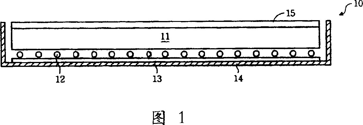
[0004] However, since the direct-type backlight assembly of the known technology distributes a plurality of lamp tubes evenly on the lower surface of the diffuse light guide plate, and the thickness of the diffuse light guide plate is usually only 2 to 4mm, the light enters from the light incident surface to the light exit surface. The emitted light guide path is too short, and the number of times the light is scattered by the diffuse particles inside the diffuse light guide plate is limited, so that the light inside the diffuse light guide plate cannot be evenly diffused, and cannot be diffused in the diffuse light guide plate. Uniform light output from the light exit surface
In addition, because the known technology is to cover the lamp tube and the backlight assembly as a whole, the heat dissipation effect of the backlight assembly as a whole will be deteriorated, so that the high heat generated by the lamp tube is easily accumulated inside the backlight assembly, and then diffused The light guide plate is transmitted to the liquid crystal display above it, which affects the liquid crystal inside the liquid crystal display
Moreover, due to the high shading rate of the diffuse light guide plate, relatively, the luminous flux of the light inside the diffuse light guide plate is also reduced, which affects the overall brightness of the backlight assembly and the viewing quality of the liquid crystal display.

Method used


Image

  • Hollow type back illumination beam component
  • Hollow type back illumination beam component
  • Hollow type back illumination beam component

Examples


Embodiment Construction

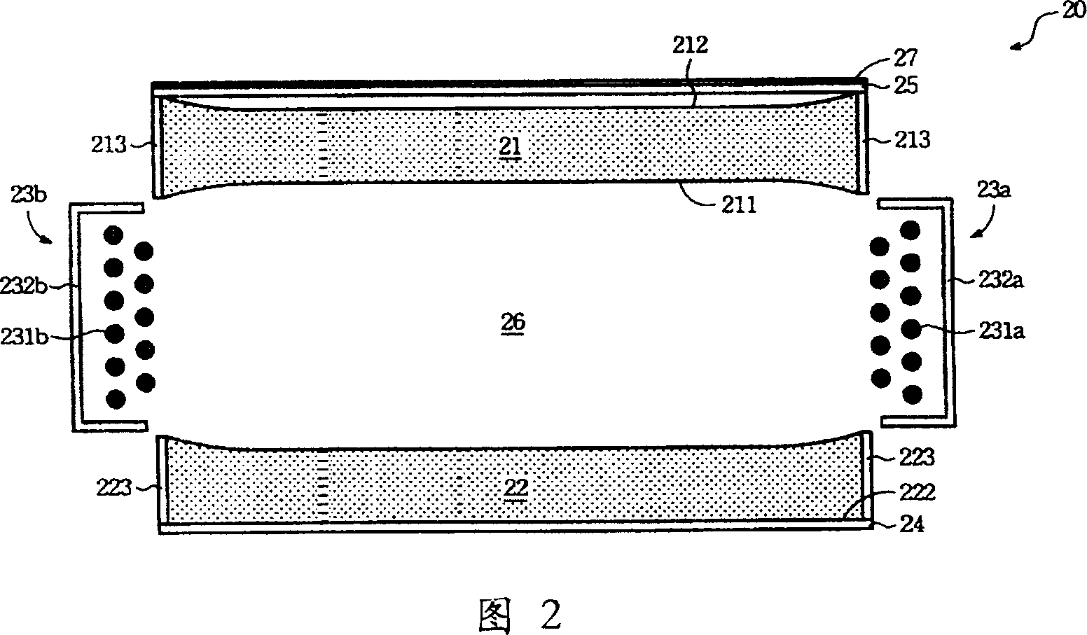
[0028] The present invention discloses a hollow backlight assembly. The hollow backlight assembly can output light evenly in terms of structural design, and obtain higher luminous flux and heat dissipation efficiency. The best embodiment and related implementation modes will be described as follows The content is described in detail.

[0029] 2 is a schematic diagram of a hollow backlight assembly 20 of the present invention, the assembly 20 includes a first light guide plate 21 , a second light guide plate 22 , two side light sources 23 , a reflective sheet 24 and a diffuser plate 25 .

[0030] The first light guide plate 21 in the figure is a light-transmitting acrylic resin plate, which includes a first inner surface 211 and a first outer surface 212. The above-mentioned two surfaces are designed as concave curved surfaces, and its purpose is to make the second A light guide plate 21 has a diffusion effect similar to a concave lens. In addition, reflective tapes 213 are pa...


PUM


Abstract

The invention relates to a hollow backlight component, including a first light guide board, a second light guide board, two side light sources, a reflection sheet and a diffusing board, where there is a hollow light guide region formed between the tow light guide boards, the two side light sources are set on two sides of the hollow light guide region, respectively, the reflection sheet is on the outer surface of the second light guide board and the diffusing board is on the outer surface of the first light guide board, the lights of the two side light sources enter into the hollow light guide region and then enter into the first and second light guide boards, respectively, the reflection sheet can reflect the light transmitted from the second light guide board to the hollow light guide region, and the diffusing board can diffuse and uniformly output the light exported from the first light guide board.

Description

technical field [0001] The invention relates to a backlight assembly of a liquid crystal display, in particular to a hollow backlight assembly. Background technique [0002] With the rapid progress of thin-film liquid crystal display (TFT-LCD) manufacturing technology, and its advantages of thinness, power saving, and radiation-free, liquid crystal displays are widely used in personal digital assistants (PDAs), notebook computers, Digital cameras, camcorders, mobile phones and other electronic products. Coupled with the industry's active investment in research and development and the adoption of large-scale production equipment, the quality of liquid crystal displays has been continuously improved, and the price has been continuously reduced, so that the application fields of liquid crystal displays have rapidly expanded. However, since the liquid crystal display is a non-luminescent display device, it needs a backlight assembly to produce a display function. [0003] Fig....

Claims


Application Information

Patent Timeline
Patent Type & Authority Patents(China)
IPC IPC(8): G02F1/13357G02B5/02G02B6/00F21V8/00G02F1/1335
Inventor 杨邦伦
Owner BENQ CORP
Learn More