
Radiation device for electronic element

A technology for heat dissipation devices and electronic components, applied in the direction of electrical components, electric solid devices, circuits, etc., can solve the problems that the cooling efficiency of computers has not been improved, and the cooling efficiency cannot meet the actual needs, so as to improve heat dissipation efficiency and avoid volume increase big effect

Inactive Publication Date: 2007-04-04
ARIMA COMP
View PDF4 Cites 0 Cited by
  • Summary
  • Abstract
  • Description
  • Claims
  • Application Information

AI Technical Summary

Problems solved by technology

However, for high-power CPUs, the cooling efficiency of this cooling device still cannot meet actual needs.
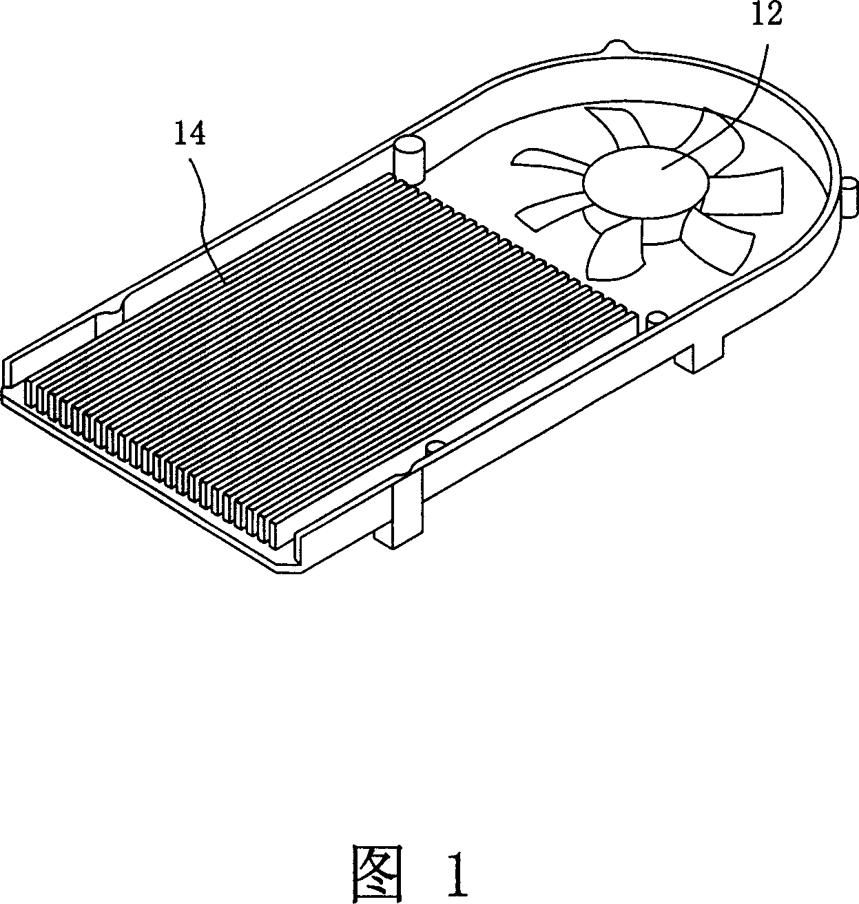
[0005] In order to improve the heat dissipation efficiency, the cooling air is drawn directly from the outside of the notebook computer, which can effectively improve the cooling effect of the CPU, but the cooling efficiency of the entire computer has not been improved, so a larger cooling fan is required to provide cooling for the CPU and the inside of the computer system. required for heat dissipation

Method used


Image

  • Radiation device for electronic element
  • Radiation device for electronic element
  • Radiation device for electronic element

Examples


Embodiment Construction

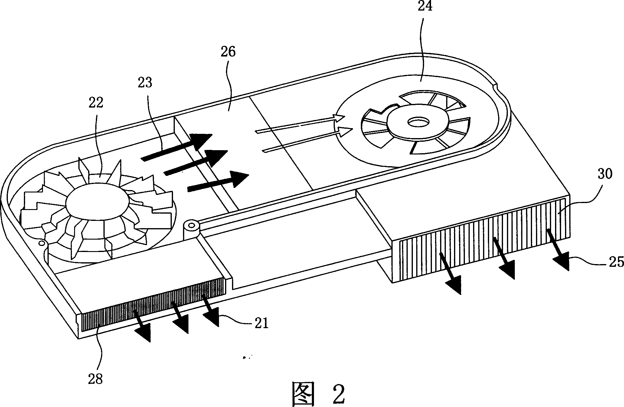
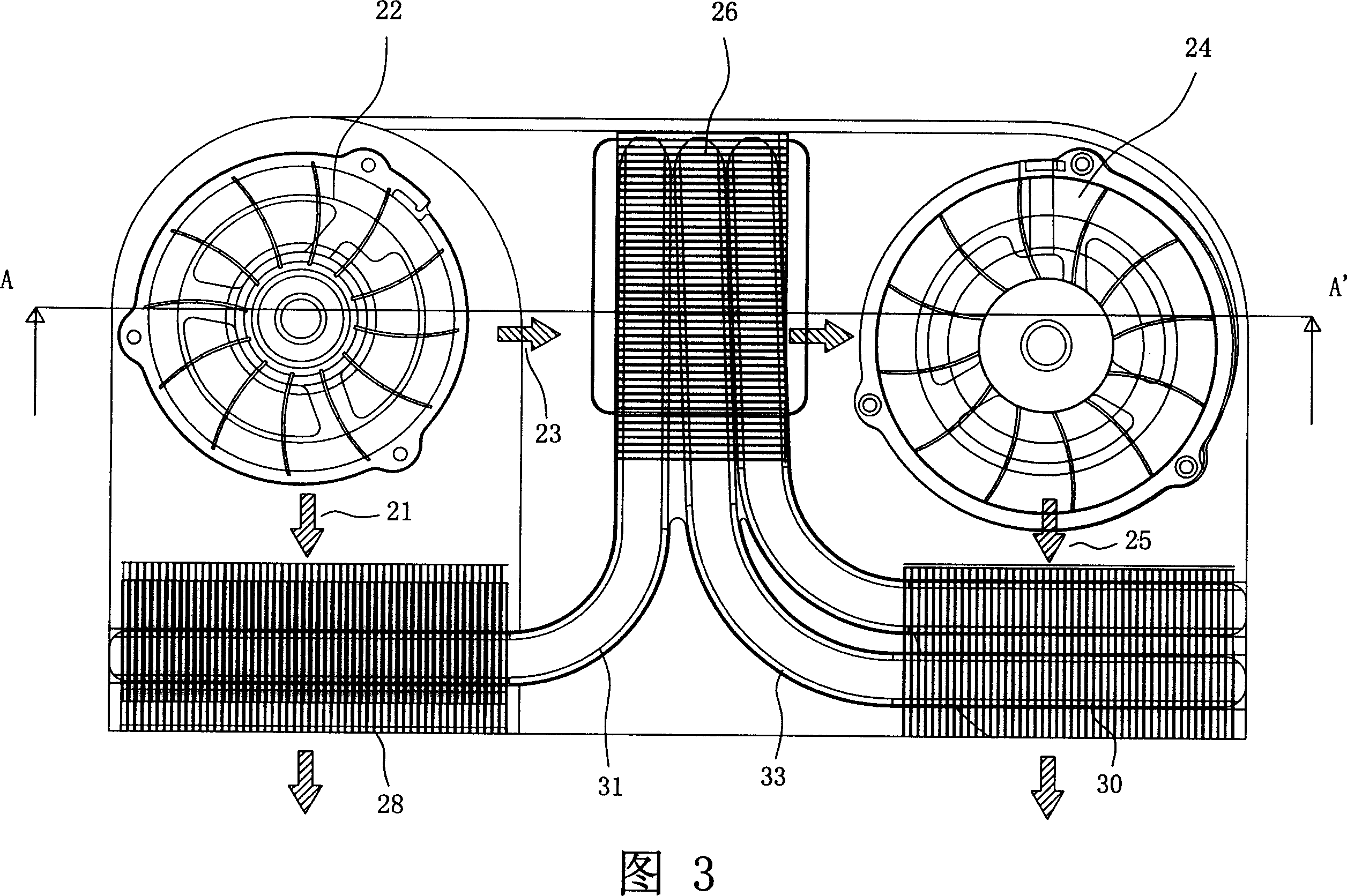
[0026] Please refer to FIG. 2 , which is a top view of a heat sink according to a preferred embodiment of the present invention. The embodiment of the present invention includes two fans and three heat sinks, and the design of using two fans in series for heat dissipation and parallel heat dissipation can reduce the volume of the heat dissipation device and increase the efficiency of heat dissipation. The so-called parallel heat dissipation means that a certain heat source (such as a CPU) is dissipated simultaneously by the airflow blown by two fans, but the airflows driven by the two fans are independent of each other. For example, in FIG. 2 , the heat sink 28 and the heat sink 30 are respectively connected to the heat source with heat pipes, and the fan 22 and the fan 24 are used to take away heat from the heat sink 28 and the heat sink 30 respectively. Therefore, the airflow flowing in the fan 22 and the heat sink 28 is independent from the airflow flowing in the fan 24 and...


PUM


Abstract

The invention is a cooling device to lower the temperature of electronic component, containing a first fan, a second fan and three fins. The first fin is linked with the electronic component by the hot tube and uses the air current from the first fan to lower the temperature; the second one is linked with the electronic component by the hot tube and uses the air current from the second fan to lower the temperature; the third one is tightly linked with the heat source of the electronic component, situated between the two fans and use the series pressure air current of the two fans to lower the temperature.

Description

technical field [0001] The invention relates to a cooling device for electronic components, in particular to a cooling device for electronic components in a notebook computer. Background technique [0002] With the rapid development of information technology and the popularization of computer applications, portable devices, such as notebook computers, etc., and precision electronic instruments are widely used. At the same time, with the rapid advancement of electronic technology and the pursuit of portability and practicality, the portable electronic products currently on the market tend to be light, thin, short, and small to meet the lifestyle of modern society. Among them, the notebook computer is a very typical example, because it has the powerful function of processing a large amount of digital information, it is liked and widely used by the public. [0003] Compared with the improvement of the manufacturing process of the integrated circuit and the increasing requireme...

Claims


Application Information

Patent Timeline
IPC IPC(8): H01L23/427H05K7/20G06F1/20H01L23/34
Inventor 邱英哲
Owner ARIMA COMP
Learn More