Configuration memory implementation for lut-based reconfigurable logic architectures

A technology for reconfiguration and memory cells, applied in the field of address decoders, which can solve problems such as affecting the quality of terminal equipment

A technology for reconfiguration and memory cells, applied in the field of address decoders, which can solve problems such as affecting the quality of terminal equipment

CN1311637CInactive Publication Date: 2007-04-18NXP BV

Image

  • Configuration memory implementation for lut-based reconfigurable logic architectures
  • Configuration memory implementation for lut-based reconfigurable logic architectures
  • Configuration memory implementation for lut-based reconfigurable logic architectures

Examples


Embodiment Construction

[0032] Therefore, first some currently known related solutions will be described in more detail. Embodiments according to the present invention will then be described in more detail. The configuration memory architecture and its implementation are largely determined by the programming method chosen for any RL device. In current RL devices, three basic programming (configuration) methods can be identified. They are:

[0033] 1. Serial configuration

[0034] 2. Parallel configuration

[0035] 3. Serial-parallel configuration.

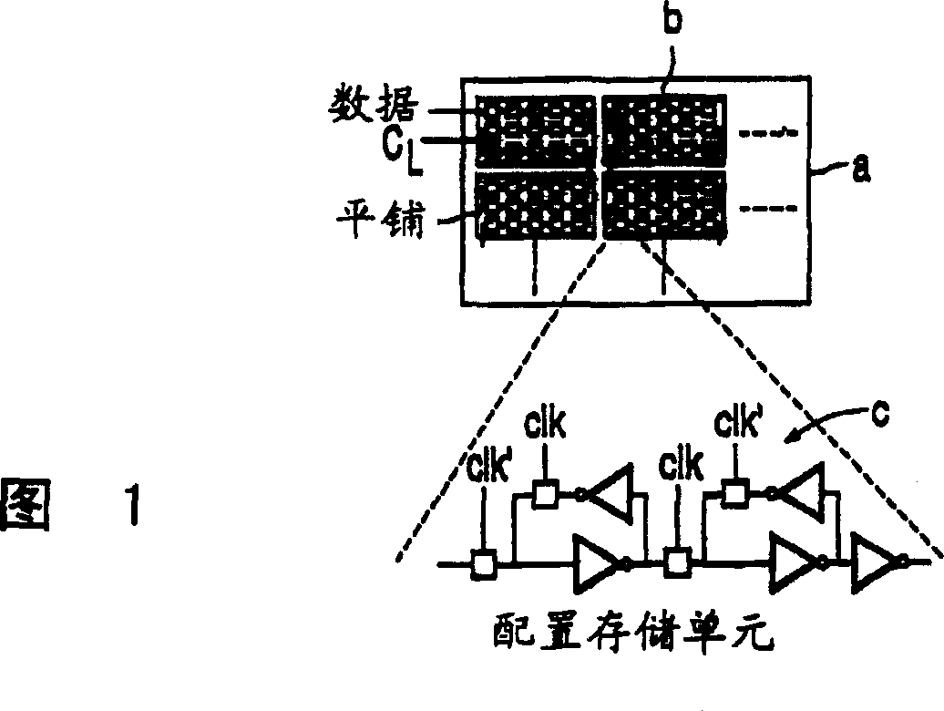
[0036] Figure 1 schematically shows a reconfigurable device, which is reconfigured in a serial configuration method. According to this method, the programming of the RL device is performed serially. To achieve this, configuration memory cells c of all tiles b of device a are connected in a single long scan chain. Data bits in such a scan chain are shifted with successive clock pulses. The advantage of this scheme is that only two pins are needed t...


PUM


Abstract

A reconfigurable processing unit (1) is described which comprises, data flow controlling elements (10), data manipulating elements (20), a configuration memory unit (30) comprising a plurality of memory cells (31a, ....) for storing settings of the data flow controlling elements (10) and an addres decoder (40) for converting an address into selection signals for the memory cells (31a, ..). The reconfigurable processing unit of the invention is characterized in that the address decoder (40) is shared between the configuration memory unit (30) and a further memory unit (20), or between two configuration memory units (30, 30'). This provides for a reduction in memory area of the reconfigurable processing unit (1).

Description

technical field [0001] The invention relates to a reconfigurable processing unit, comprising a data flow control element, a data manipulation element, a configuration memory unit including a plurality of storage units for storing settings of the data flow control element, and a configuration memory unit for converting addresses into Address decoder for cell select signals. Background technique [0002] Reconfigurable logic devices include data flow control elements, such as multiplexers, demultiplexers, gates, etc., and data manipulation elements, such as logic gates, adders, and look-up tables, or elements that can be so configured . The latter allows implementing different functions, which can be easily redefined by loading them with different configuration content. The reconfigurable logic device further includes a configuration memory unit (configuration memory) for storing settings of data flow control elements, such as multiplexers, demultiplexers, switches, etc. In...

Claims


Application Information

Patent Timeline
18 Apr 2007
Publication
CN1311637C
IPC
H03K19/173; H03K19/177; G06F15/78
CPC
G06F15/7867; H03K19/1776
Inventors
K·赖坦-诺瓦克