Non-invasive imaging of retinal function

A retinal and functional technology, applied in the field of non-invasive imaging systems, can solve the problem of failing to reveal functional retinal signals

Inactive Publication Date: 2001-10-10
YEDA RES & DEV CO LTD
View PDF1 Cites 4 Cited by
  • Summary
  • Abstract
  • Description
  • Claims
  • Application Information

AI Technical Summary

Problems solved by technology

But the method of said patent fails to reveal the functional retinal signal, as this method is specified to do

Method used


Image

  • Non-invasive imaging of retinal function
  • Non-invasive imaging of retinal function

Examples


Embodiment Construction

[0018] Detailed description of the preferred embodiment

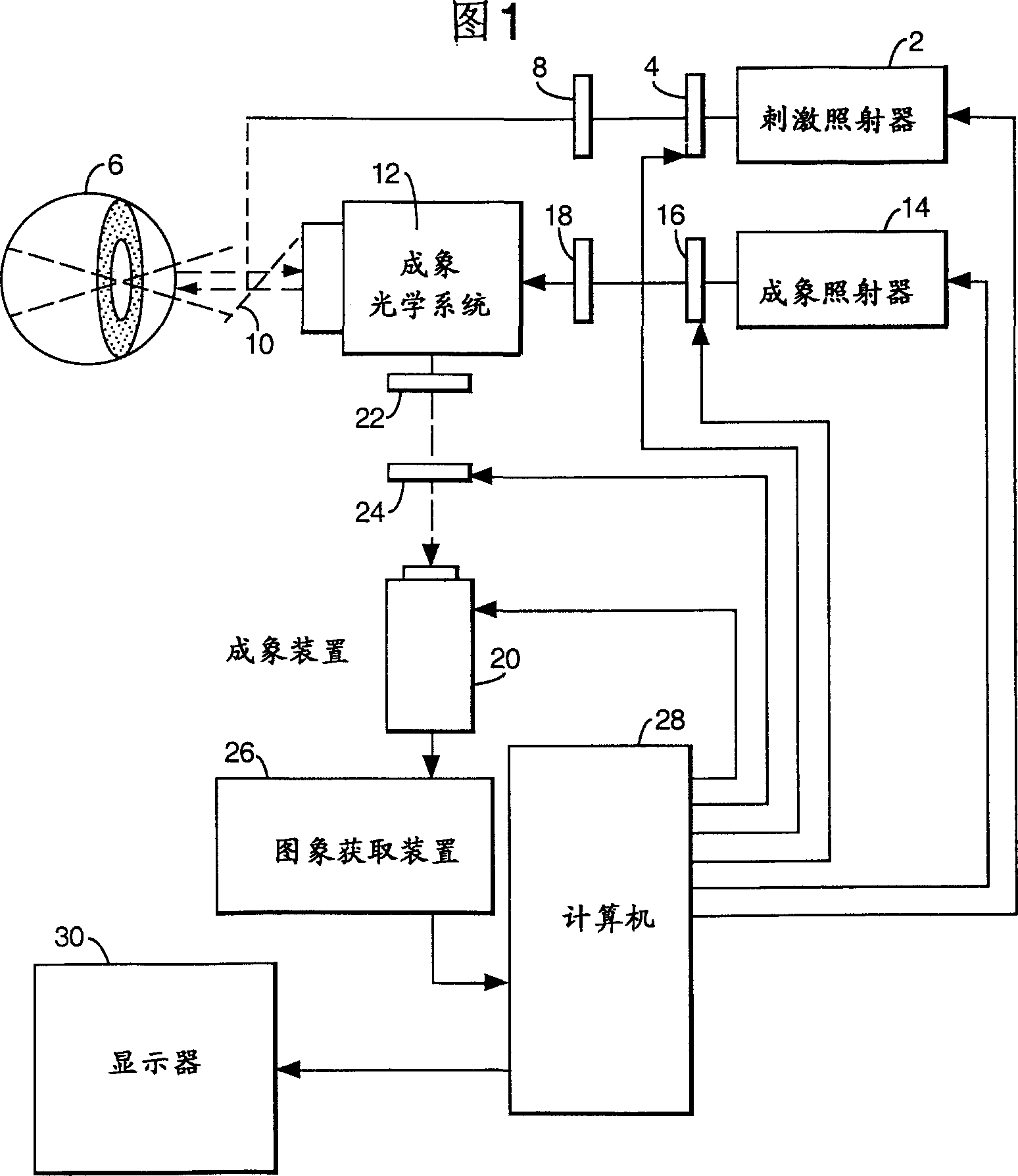
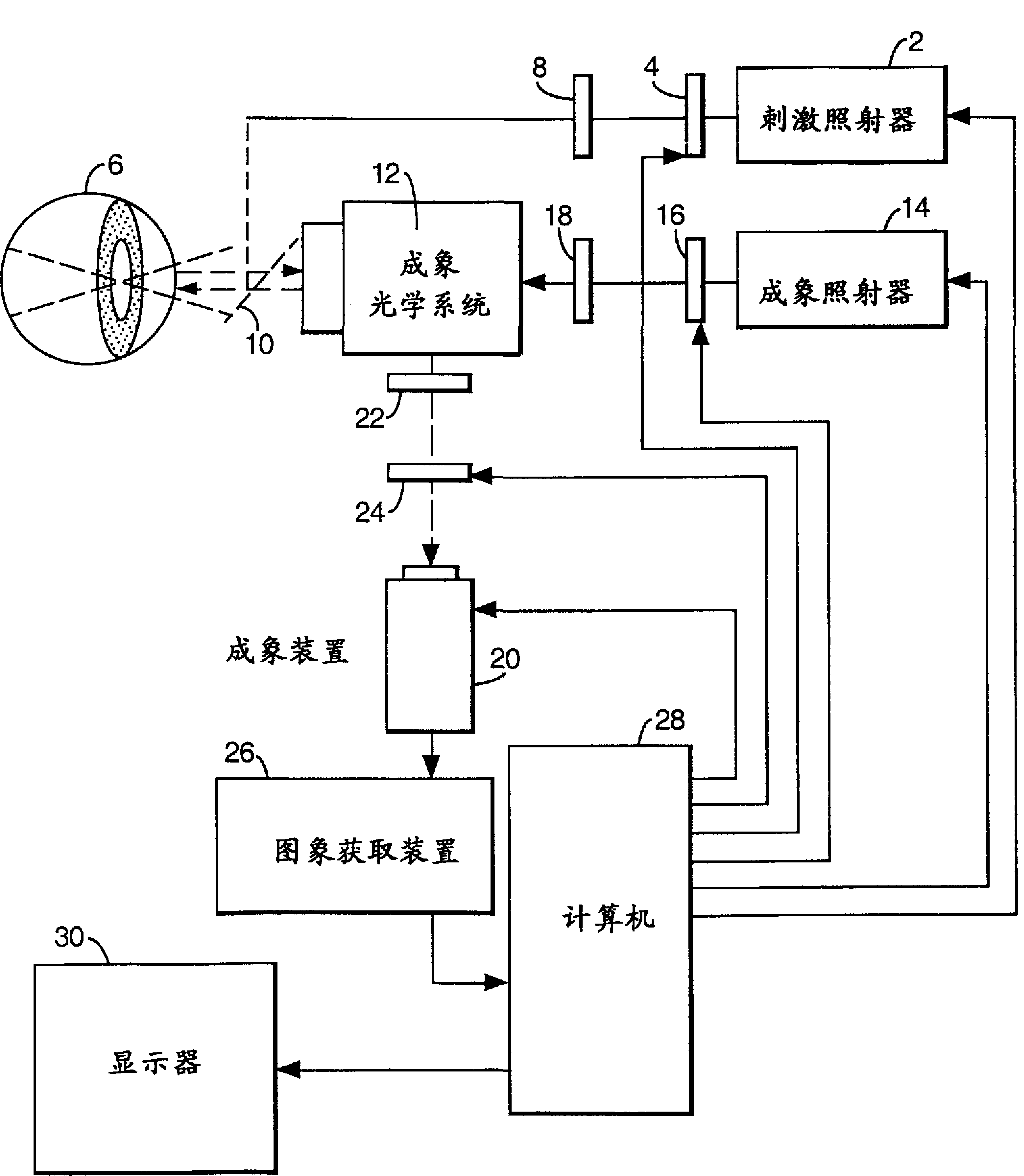
[0019] In Fig. 1 there is an external stimulus illuminator 2, which may be constituted by a computer monitor or any other image display device for controllably displaying visual objects. The shutter 4 can also be arranged in the optical path between the illuminator 2 and the retina 6 of the patient's eye. The display of the illuminator 2 is controlled by relative duration, timing, wavelength, pattern or intensity. In order to control the wavelength of light more precisely, an optical wavelength filter 8 can be placed between the stimulus image and the eye. The image enters the retina 6 via a partial mirror 10 situated between the eye and an (ophthalmic) imaging optics 12 . At the same time, this external stimulus irradiation can be brought to the retina 6 by the imaging optical system 12 itself. Obviously, other external stimulus illumination devices can produce functional retinal imaging, including those using image...


PUM


Abstract

The invention provides a system for imaging reflectance changes, intrinsic or extrinsic fluorescence changes of a retina (6) due to retinal function, including an imaging illuminator (14) for illumination of the retina (6); a retina-stimulating illuminator (2) for inducing a functional response; an imaging device (20) receiving light from the retina (6) via retinal imaging optics (12); image acquisition means (26) for digitizing and storing images received from the imaging device (20), and a computer (28) for controlling the operation of the system and for processing the stored images to reveal a differential functional signal corresponding to the retina's function.

Description

field of invention [0001] The present invention relates to systems and methods for non-invasive imaging of retinal function. Background of the invention [0002] In some degenerative retinal diseases, retinal function can be altered even before changes in retinal tissue detectable by current, ineffective diagnostic imaging techniques occur. In glaucoma, for example, more than 50% of the retinal axons degenerate before signs of pathology or even a reduction in visual acuity noticed by the patient. Due in part to the limitations of current diagnostic techniques, it is estimated that more than 3,000,000 patients in the United States are undiagnosed victims of only commonly treatable visual impairment. [0003] Commonly prevalent ophthalmic diagnostic imaging techniques, such as retinal photography, fluorescein angiography, and retinal tomography, do not directly reveal the functional state of the retina. Retinal photography detects abnormalities in static retinal pigmentation...

Claims


Application Information

Patent Timeline
Patent Type & Authority Applications(China)
IPC IPC(8): A61B3/12G06T1/00
CPCA61B3/1241A61B3/12
Inventor 阿米兰·格林瓦尔德达林·纳尔逊
Owner YEDA RES & DEV CO LTD
Why Eureka
Try Eureka