Method and apparatus for optical imaging of retinal function
a retinal function and optical imaging technology, applied in the field of optical imaging of retinal function, can solve the problems of not detecting any functional problem at all, and conventional general ophthalmic diagnostic imaging technologies are incapable of directly detecting the functional structure of the retina, and achieve excellent such effects and high reliability
- Summary
- Abstract
- Description
- Claims
- Application Information
AI Technical Summary
Benefits of technology
Problems solved by technology
Method used
Image
Examples
first embodiment
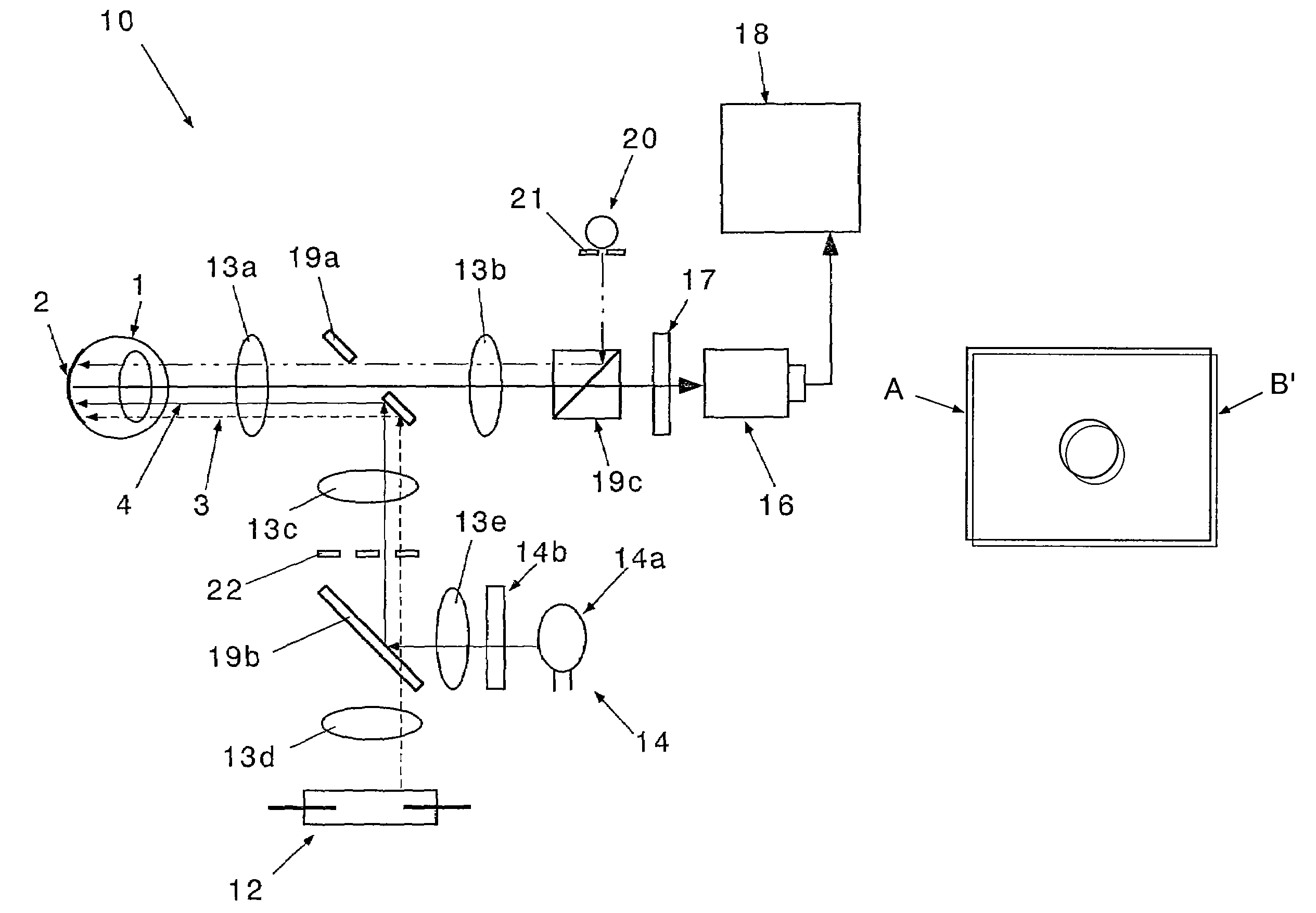
[0078]Referring to FIGS. 5A and 5B, there are shown the images before and after the stimulation. The image B (FIG. 5B) after the stimulation, in which the neurons are active, shifts relative to the image A (FIG. 5A) immediately before the stimulation to the extent that it is unrecognizable with eyes (in this embodiment, 0.1 to 0.2 mm).
[0079]FIGS. 6A and 6B each show a first embodiment of the change of the retinal function and the optic disk's function according to the present invention or to the conventional example. The result (FIG. 6A) of dividing the retinal image B where the neurons are active by the retinal image A immediately before the stimulation according to the conventional method does not match a known typical activity pattern of the neurons of the retina, because the image B (FIG. 5B) where the neurons are active slightly shifts to the right relative to the image A (FIG. 5A) immediately before the stimulation.
[0080]On the other hand, according to the method of the presen...
second embodiment
[0085]Referring to FIG. 8, there is shown a diagram showing a second embodiment of the change of the retinal function and the optic disk's function according to the present invention and to the conventional example. In this diagram, FIG. 8A shows the embodiment of the present invention, illustrating the change of the retinal function and the optic disk's function of the retinal region enclosed by A in FIG. 8C. FIG. 8B shows an example where a visible light is used for observation and illumination, illustrating the change of the retinal function and the optic disk's function of the retinal region enclosed by B in FIG. 8C.
[0086]As shown in FIG. 8B, the example where the visible light is used for the observation and illumination does not genuinely reflect the function of the macular area. Therefore, the discoloration or change in hemoglobin caused by the stimulation is relatively large and it is impossible to detect the change of the intrinsic signal (retinal function) and the optic di...
third embodiment
[0087]Referring to FIG. 9, there is shown a third embodiment illustrating the change of the retinal function and the optic disk's function according to the present invention. In this diagram, FIGS. 9A, 9B, 9C, and 9D show a fundus photograph of a normal retina, an anatomical distribution chart of cone photoreceptors, a functional topography of the macular area with the optical imaging of the present invention, and a cross-sectional view of FIG. 9C, respectively.
[0088]In FIG. 9A, the center is the macular area, which is the area having the highest neuron function. The rectangle in this diagram represents the retinal region (recorded area) of the rear surface of the eyeball including the macular area and the optic disk.
[0089]FIG. 9B shows the distribution of cone photoreceptors on the retina, with the abscissa axis representing the angle from the center of the retina and the ordinate axis representing the number of photoreceptors per square millimeter. As apparent from this diagram, t...
PUM
 Abstract
Description
Claims
Application Information
 - R&D
- Intellectual Property
- Life Sciences
- Materials
- Tech Scout
- Unparalleled Data Quality
- Higher Quality Content
- 60% Fewer Hallucinations
Browse by: Latest US Patents, China's latest patents, Technical Efficacy Thesaurus, Application Domain, Technology Topic, Popular Technical Reports.
© 2025 PatSnap. All rights reserved.Legal|Privacy policy|Modern Slavery Act Transparency Statement|Sitemap|About US| Contact US: help@patsnap.com


