Brake servo unit comprising an emergency brake auxiliary function

A technology of brake booster and control valve, applied in the direction of brake, brake transmission, transportation and packaging, etc., can solve the problems of low cost and complex mechanical structure.

Inactive Publication Date: 2007-07-04
LUCAS AUTOMOTIVE GMBH
View PDF6 Cites 0 Cited by
  • Summary
  • Abstract
  • Description
  • Claims
  • Application Information

AI Technical Summary

Problems solved by technology

[0005] However, the solutions described last above are rather mechanically complex and are therefore not much cheaper than the previously mentioned solutions using electromagnets

Method used


Image

  • Brake servo unit comprising an emergency brake auxiliary function
  • Brake servo unit comprising an emergency brake auxiliary function

Examples


Embodiment Construction

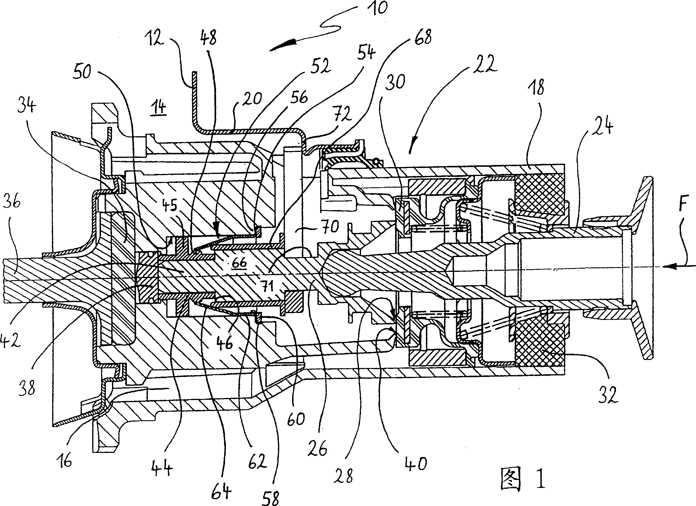
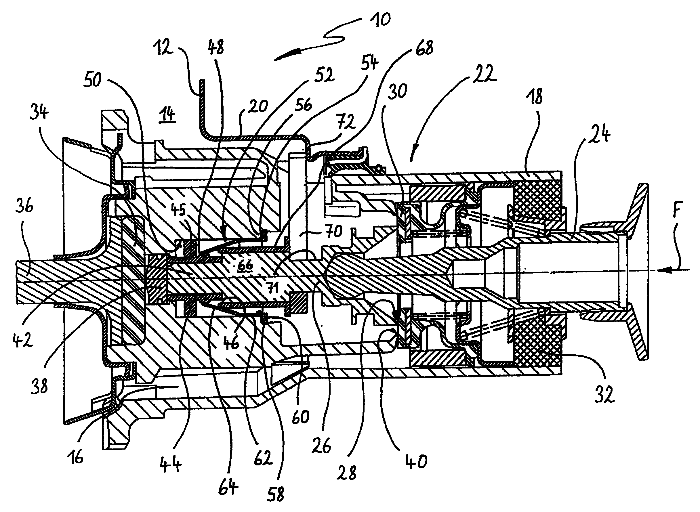
[0017] Hereinafter, an embodiment of the brake booster of the present invention will be described in detail with reference to a schematic diagram, which shows a longitudinal sectional view of the control valve of the brake booster according to the present invention.

[0018] The drawing is a longitudinal sectional view showing relevant parts of a vacuum brake booster used in a hydraulic brake system of a motor vehicle, and the vacuum brake booster as a whole is denoted by the reference numeral 10. A brake master cylinder (not shown in the figure) is connected downstream of the brake booster 10, and the brake booster 10 has a shell 12 composed of a metal plate shell. Only the initial part of the shell 12 is shown in the figure. In the housing 12, a movable wall not shown in the figure seals the working chamber 14 and the vacuum chamber 16 apart.

[0019] The movable wall is firmly connected to the control valve housing 18 which extends in a slidably movable manner within the tubula...


PUM


Abstract

A brake booster, in particular for motor vehicles, having a control valve for controlling the boosting force generated by the brake booster. The control valve comprises a control valve housing, an input element, an output element and a thrust piece, which is disposed between the input element and the output element and acts upon the output element. The thrust piece in dependence upon a relative movement between the thrust piece and the control valve housing caused by the input element is supported releasably against the control valve housing by means of a coupling element biased by a spring. The spring and the coupling element are designed as an integral coupling component, which is fastened to the control valve housing.

Description

Technical field [0001] The present invention relates to a brake booster, especially a brake booster for a motor vehicle, for example, such a brake booster is disclosed in WO99 / 26826. This kind of brake booster usually takes the form of a vacuum brake booster, and is used to provide auxiliary force to the vehicle driver during the braking operation, so that the brake driving force applied by the driver can be maintained at a constant level. Comfortable value. Purely hydraulically operated brake boosters are known, so the invention is not limited to vacuum brake boosters. Background technique [0002] Regardless of the method used to generate the auxiliary force, for example, whether the auxiliary force is generated by the vacuum method or the hydraulic method, the brake booster usually has the function of controlling the auxiliary force generated by the brake booster, that is, the control auxiliary function. A control valve and a control valve housing of the magnitude of the force...

Claims


Application Information

Patent Timeline
Patent Type & Authority Patents(China)
IPC IPC(8): B60T13/575B60T13/57B60T8/32
CPCB60T8/3275B60T13/57B60T13/575
Inventor 埃内斯托·布拉沃·比利亚马约尔
Owner LUCAS AUTOMOTIVE GMBH
Why Eureka
Try Eureka