Synchronous device for double clutch speed variator

A dual-clutch transmission and synchronizing device technology, applied in the direction of transmission, control, transmission control, etc., can solve the problems of no setting, troublesome, expensive, etc., and achieve the effects of economy and wear, reduce wear and prolong life.

Inactive Publication Date: 2007-07-11
VOLKSWAGEN AG
View PDF7 Cites 0 Cited by
  • Summary
  • Abstract
  • Description
  • Claims
  • Application Information

AI Technical Summary

Problems solved by technology

This is more complicated and requires certain components or auxiliary equipment on the engine side and the control of these additional measures is more expensive
On the contrary, there is no electronic shift process control as required by the synchronizing device of the dual clutch transmission

Method used


Image

  • Synchronous device for double clutch speed variator
  • Synchronous device for double clutch speed variator
  • Synchronous device for double clutch speed variator

Examples


Embodiment Construction

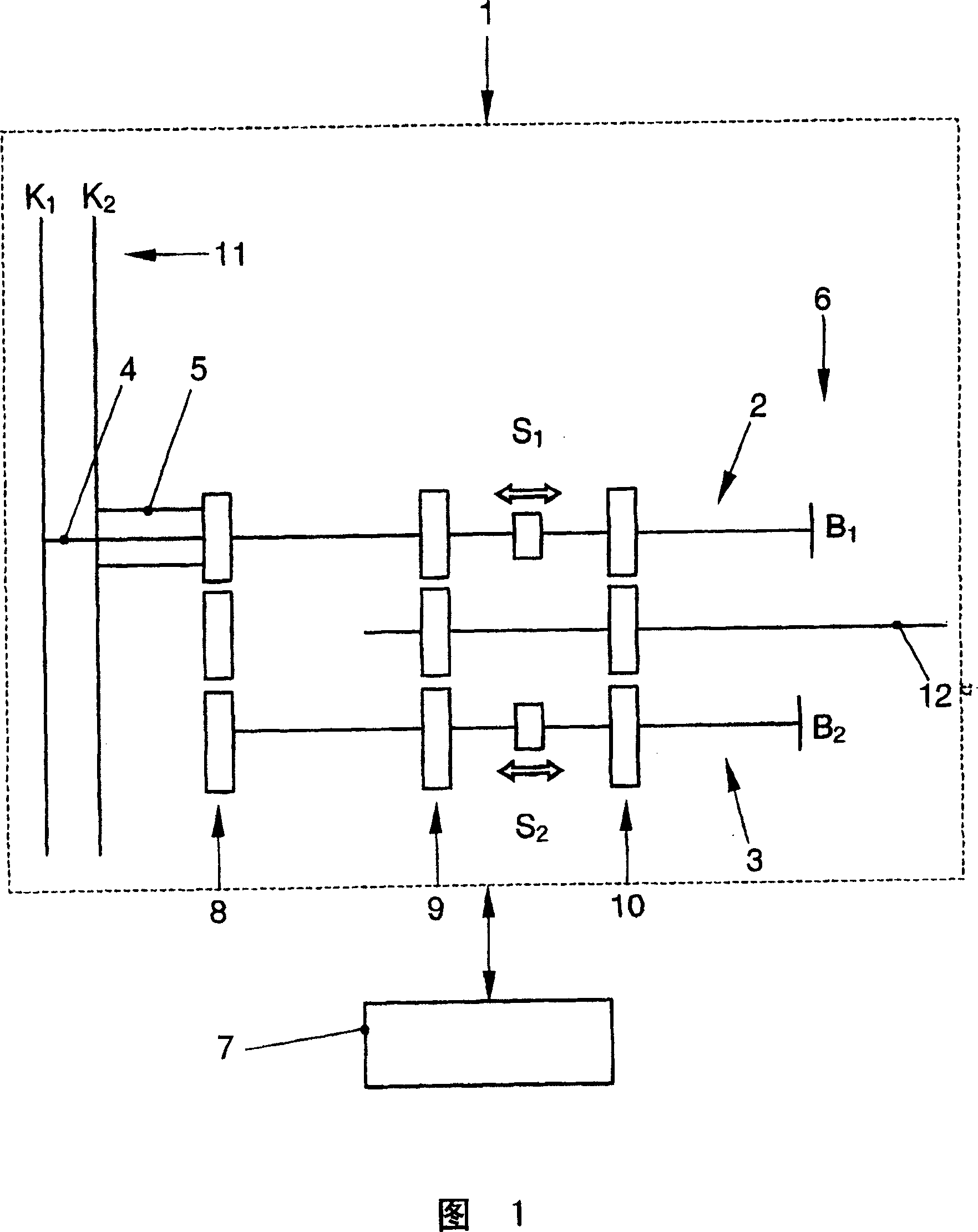
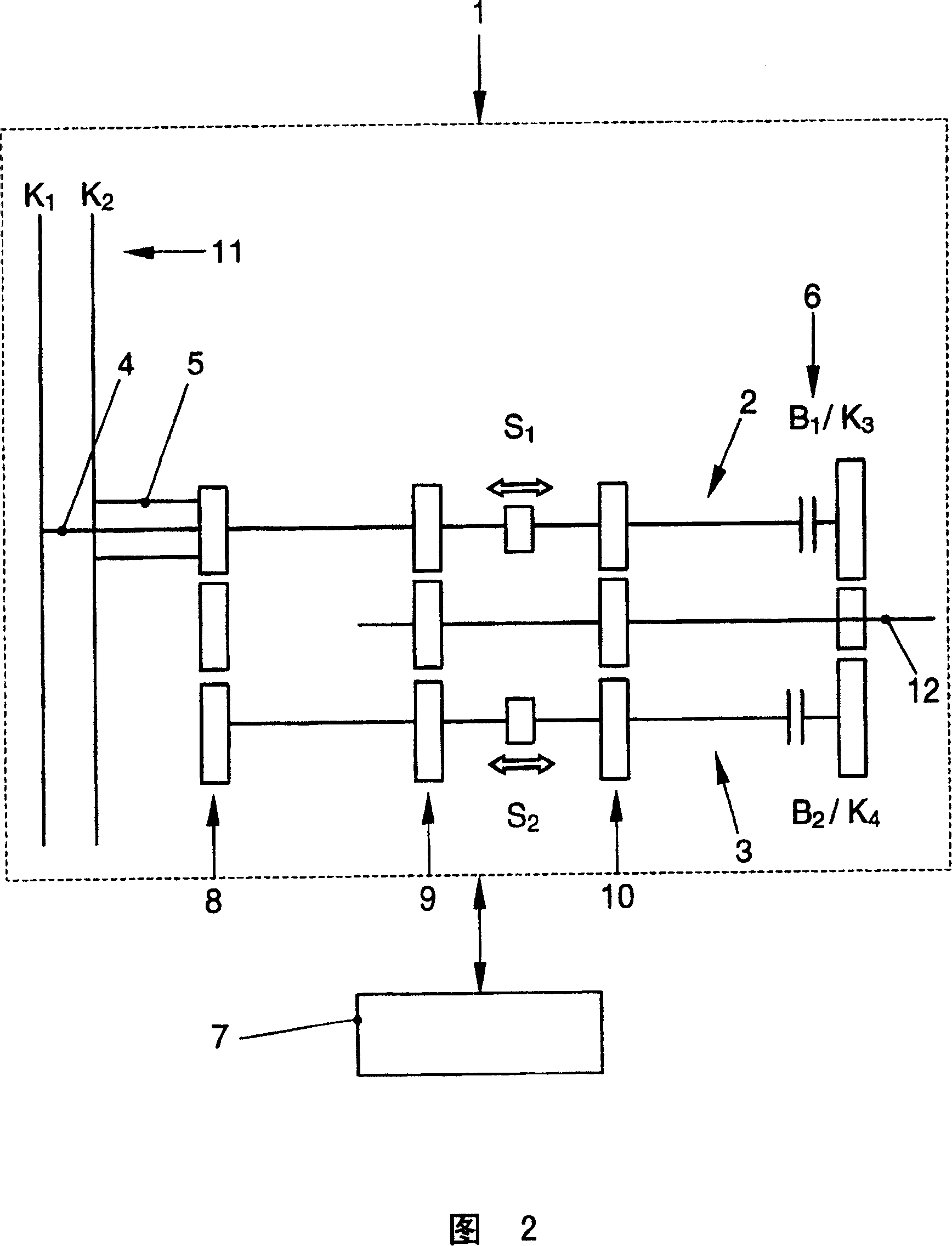
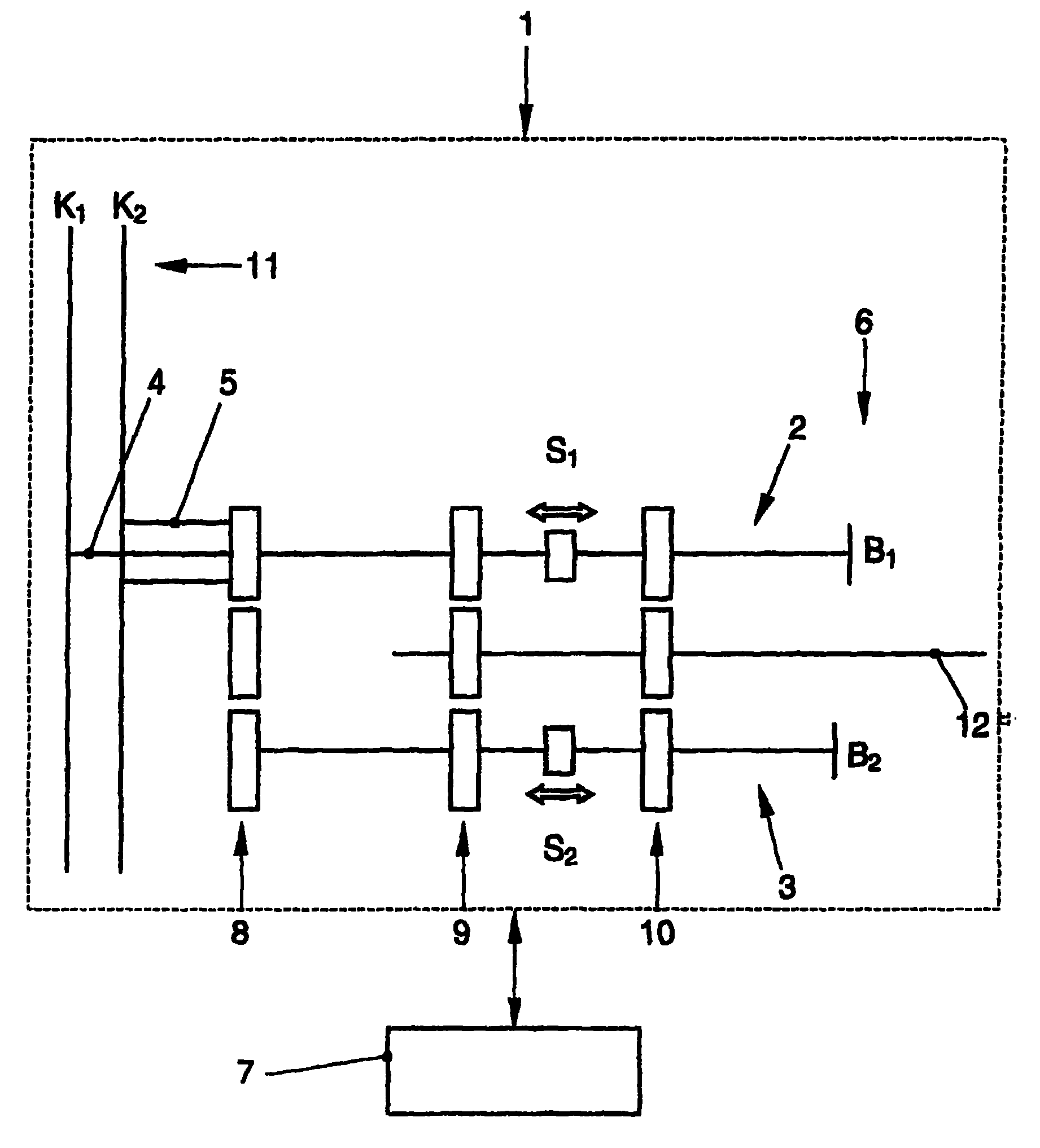
[0028] The synchronizing device 1 of the dual-clutch transmission mainly includes a braking mechanism 6 and two transmission output shaft brakes B1 and B2.

[0029]The dual clutch transmission 1 essentially comprises two subtransmissions 2 and 3 and a dual clutch 11 formed from two input clutches K1 and K2. The subtransmissions 2 and 3 are each connectable via their corresponding input clutches K1 or K2 to a drive motor (not shown) in order to transmit the drive torque via the individual gears, that is to say with a certain transmission ratio, to the transmission output shaft 12 . One sub-transmission 2 or 3 assumes odd-numbered gears, and the other sub-transmission 3 or 2 correspondingly assumes even-numbered gears. The dual-clutch transmission 1 has two coaxially arranged transmission input shafts 4 , 5 , wherein the sub-transmission 2 is assigned to the inner shaft 4 and the sub-transmission 3 is assigned to the outer shaft 5 . Here, the subtransmission 3 is engaged with ...


PUM


Abstract

The synchronization device provides braking of the rotation revs of the switched drive stage when switching from a lower gear into a higher gear, the braking device (6) for each partial drive train (2,3) of the dual-clutch gearbox (1) having a drive input shaft brake (B1,B2) operated by a control device (7), for providing a braking force for the drive input shaft (4,5) ensuring rev synchronization with the target gear stage.

Description

technical field [0001] The invention relates to a synchronizing device, especially for a dual-clutch transmission of a motor vehicle, having a brake which, when shifting from a lower source gear to a higher target gear, causes the transmission performing the shift The rotational speeds of the parts are synchronized. Background technique [0002] Dual-clutch transmissions for motor vehicles have been known for a long time. Dual-clutch transmissions generally have two coaxially arranged transmission input shafts, each of which has an independent input clutch and a set of gears and a transmission output shaft or driven shaft. Known dual clutch transmissions use, for example, two oil-cooled multi-plate clutches or wet clutches as input clutches. Usually one set includes odd gears and reverse, and the other set includes even gears. In principle, each gear group has a fixed wheel, which is connected in a rotationally fixed manner to one shaft, and which meshes continuously with...

Claims


Application Information

Patent Timeline
Patent Type & Authority Patents(China)
IPC IPC(8): B60K20/00F16H59/00F16H61/04F16H61/688
CPCF16H2003/123F16H61/0403F16H2306/48F16H2061/0411F16H61/688F16H3/006
Inventor W·-R·卢茨G·克鲁泽
Owner VOLKSWAGEN AG
Why Eureka
Try Eureka