Spiraling device

A spiral winding and spiral-shaped technology, applied in the field of spiral winding devices, can solve the problems of difficult access to yarn bobbins, high installation and adjustment costs, and achieve uniform yarn tension, simple production and maintenance, and easy installation and adjustment. Monitor the effect of optimization

Inactive Publication Date: 2007-07-25
CONTITECH LUFTFEDERSYST
View PDF5 Cites 0 Cited by
  • Summary
  • Abstract
  • Description
  • Claims
  • Application Information

AI Technical Summary

Problems solved by technology

[0007] The disadvantage is that it is difficult to access each yarn bobbin with the corresponding yarn, so that the set-up time and required set-up costs are relatively large
In particular, uniform yarn tension for all yarns cannot be guaranteed to a great extent

Method used


Image

  • Spiraling device
  • Spiraling device

Examples


Embodiment Construction

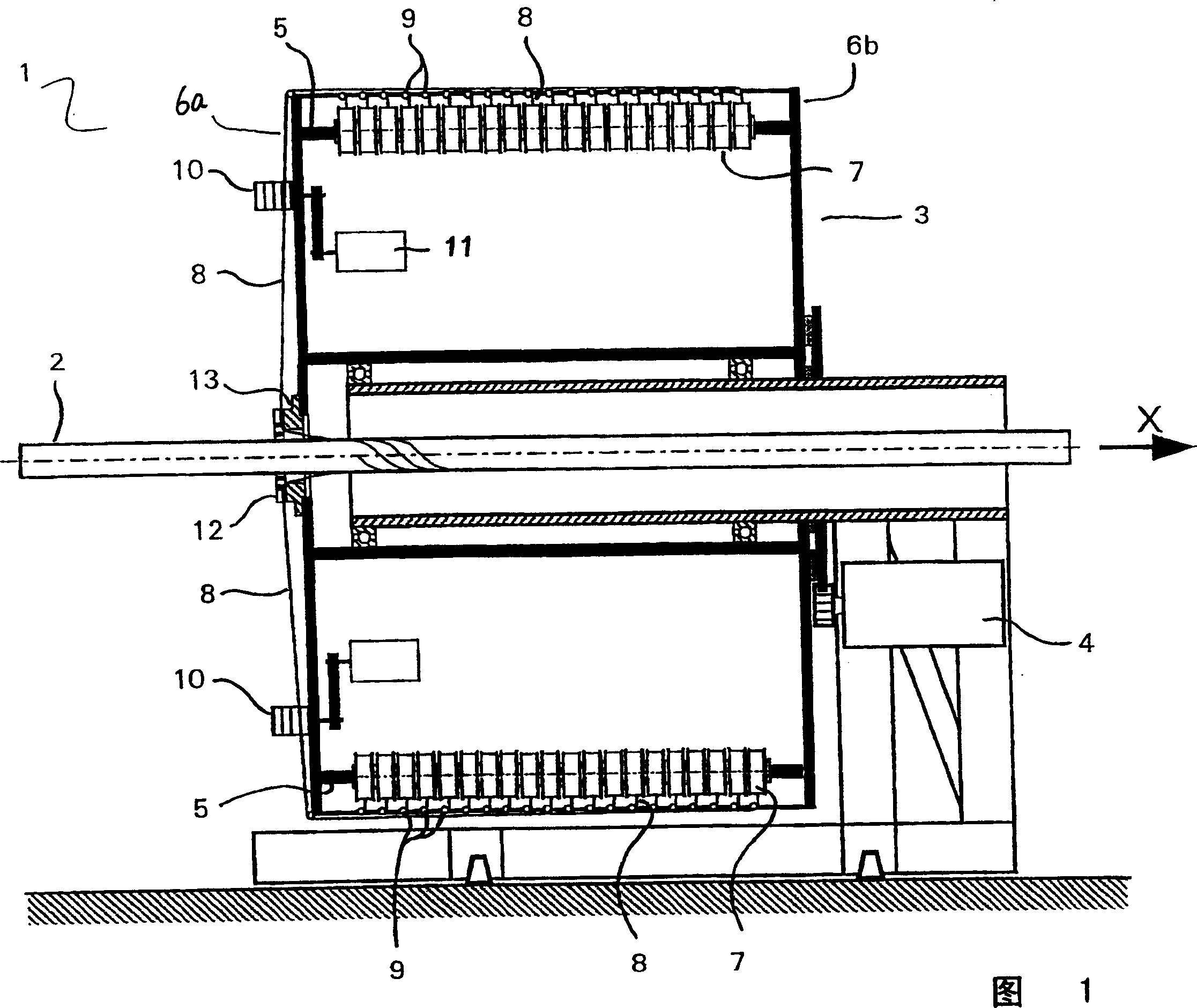
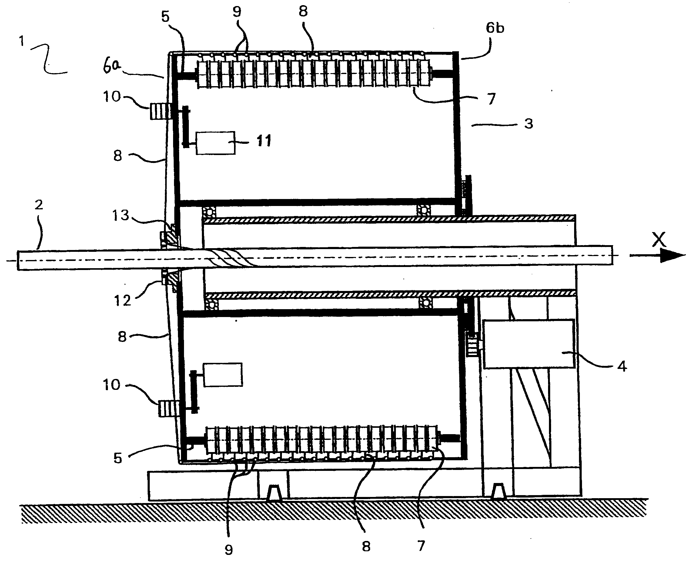
[0023] FIG. 1 shows a cross-section through a spiral wound device 1 according to the invention. A carriage 2 - for example juxtaposed cylindrical tubes with at least one rubber layer pressed against the tube - is guided through the center of the helical winding device 1 along the longitudinal axis X of the carriage and moved forward. The spiral winding device 1 has a rotor 3 which is driven by a transmission unit 4 and rotates about the longitudinal axis of the carriage 2 . A plurality of yarn bobbin-carrier shafts 5 are distributed over at least one circumferential radius of the rotor 3 . The yarn bobbin-carrier shaft 5 extends between a first end face 6a and a second end face 6b of the rotor 3 and is inserted preferably detachably into the snap-in mechanism. Each yarn bobbin-carrier shaft 5 serves to accommodate a plurality of yarn bobbins 7 which are mounted rotatably in the direction of the carrier longitudinal axis X on the yarn bobbin-carrier shaft 5 . The axis of the ...


PUM


Abstract

Disclosed is a spiraling device (1) for applying a spiral-shaped threaded layer to an elongate support (2) that can be advanced in the direction of the longitudinal axis (X) thereof. Said spiraling device (1) comprises a rotor that is rotatable around the longitudinal axis (X) of the support, a plurality of thread bobbin-supporting shafts (5) which extend in the direction of the longitudinal axis (X) of the support, are disposed at a distance from each other along a peripheral radius of the rotor (3), and are configured so as to receive a plurality of thread bobbins (7). Thread-braking elements (10) which can be triggered in a mutually synchronous manner are arranged at a distance from each other on a face (6a) of the rotor (3) along the periphery thereof. The threads (8) are removed from the bobbins (7) and are directed to the support (2) via the thread-braking elements (10) and a cam ring (12) enclosing the support (2) by means of thread-guiding elements (9).

Description

technical field [0001] The invention relates to a spiral winding device for stacking spiral yarn layers on an elongated carrier, which is movable forward in the direction of its longitudinal axis. The spiral winding device has a rotor that can rotate around the longitudinal axis and many yarn bobbins-carrier shafts extending in the direction of the longitudinal axis of the carriage. These yarn bobbins-carriage shafts are distributed on a circumferential radius of the rotor and are respectively Good for holding many yarn bobbins. Background technique [0002] In particular to increase the strength of rubber hoses, plastic hoses, rubber tubes or plastic tubes with a strength carrier layer, the thick yarn layer is helically wound onto the plastic or rubber carrier with at least one helical winding device. One such production method is described, for example, in German Utility Models 1928736 and DE3824757A1. In this case, the yarn is unwound from a plurality of yarn bobbins ar...

Claims


Application Information

Patent Timeline
Patent Type & Authority Patents(China)
IPC IPC(8): B29C53/80B29D23/20B65H81/06B29C53/66B29C70/16B29L23/00
CPCB29C53/8016B65H59/16B29C70/16B65H49/32B29C53/80B29D23/20B65H81/06
Inventor M·伯格尔R·厄尔K·宾德
Owner CONTITECH LUFTFEDERSYST
Why Eureka
Try Eureka