Start controller for engine

A starting control device and engine technology, which is applied to the starting of the engine, engine control, starting of the motor for the engine, etc., and can solve problems such as insufficient power supply

Inactive Publication Date: 2002-01-30
HONDA MOTOR CO LTD
View PDF2 Cites 8 Cited by
  • Summary
  • Abstract
  • Description
  • Claims
  • Application Information

AI Technical Summary

Problems solved by technology

However, the electric power supply is still insufficient for recent vehicles that further in

Method used


Image

  • Start controller for engine
  • Start controller for engine
  • Start controller for engine

Examples


Embodiment Construction

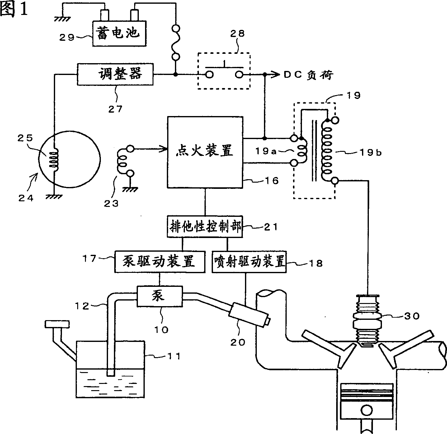
[0014] Hereinafter, the present invention will be described in detail with reference to the drawings. Fig. 1 is a block diagram showing the configuration of main parts of an engine start control device using the present invention.

[0015] The fuel stored in the fuel tank 11 is sucked by the fuel pump 10 and supplied to the fuel injector 20 via the fuel pipe 12. The fuel pump 10 is driven by the pump driving device 17, and the fuel injection nozzle 20 is driven by the injection driving device 18. The output voltage of the battery 29 is supplied to the ignition device 16 and the DC load through the main switch 28. The ignition device 16 controls the power supply to and disconnection of the ignition coil 19 and supplies ignition energy to the spark plug 30.

[0016] The ignition coil 19 includes a primary coil 19a to which a DC voltage is applied and a secondary coil 19b that generates a high voltage corresponding to the change in current of the primary coil 19a. The ignition device...


PUM


Abstract

A starting control device of engine capable is provided. An exclusive control part 21 controls an energization to each system such that at least one of a pump system including a fuel pump 10, an injection system including an injector 20 and an ignition system including an ignition unit 16 is timely divided or is exclusively driven regarding at least one of another system.In this way, by ensuring a current fed to respective devices by exclusively driving a device unnecessary for being always simultaneously driven at the time of starting the engine, can further improve a starting property of the engine.

Description

Technical field [0001] The present invention relates to a start control device for an engine provided with a fuel injector, and more particularly to an engine start control device that can obtain good startability even when the discharge capacity of a battery is reduced. Background technique [0002] When the engine is started, it is particularly necessary to supply sufficient power to the ignition coil. For this reason, when the discharge capacity of the battery decreases, even if you want to start the engine when loads such as headlamps with high power consumption are energized, sufficient power cannot be supplied to the ignition coil, and there is a problem that the startability of the engine decreases. [0003] In order to solve this problem, Japanese Patent Laid-Open No. 4-132877, Utility Model Registration No. 2518904, or Shikai Hei 2-18786 proposes to temporarily remove the load of headlights and other lights from the power line when the engine is started. Disconnected eng...

Claims


Application Information

Patent Timeline
IPC IPC(8): F02P3/045F02D17/00F02D29/02F02D41/06F02D41/32F02D43/00F02D45/00F02M37/08F02N11/08F02N99/00F02P9/00
CPCY02T10/123Y02T10/12F02D43/00F02N11/08
Inventor 田中弘志熊谷千昭
Owner HONDA MOTOR CO LTD
Why Eureka
Try Eureka