Chemical canchoring adhesive rope

An adhesive and anchoring technology, which is applied in the direction of adhesive type, adhesive, film/sheet adhesive, etc., can solve the problem of leaking out and drifting out with the wind in horizontal drilling, insufficient viscosity, multiple Packaging waste and other issues

Inactive Publication Date: 2002-02-06
ILLINOIS TOOL WORKS INC
View PDF2 Cites 1 Cited by
  • Summary
  • Abstract
  • Description
  • Claims
  • Application Information

AI Technical Summary

Problems solved by technology

Disadvantages of adhesives in cartridges include: excess packaging waste; excessive adhesive waste due to unmixing; unused material remaining in the caulking bucket; and insufficient viscosity causing material to drill holes from vertical overhead leak out and drift out in horizontal boreholes

Method used


Image

  • Chemical canchoring adhesive rope
  • Chemical canchoring adhesive rope
  • Chemical canchoring adhesive rope

Examples


Embodiment Construction

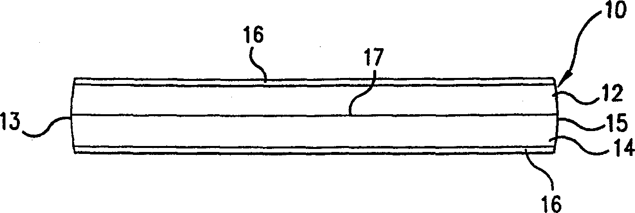
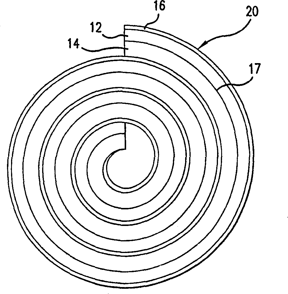
[0022] The invention relates to a chemical anchoring adhesive rope. refer to figure 2 , the rope 20 may be wound into a roll for storage and uncoiled for use. Adhesive strand 20 includes a first portion 12 comprising a resinous component and a second portion 14 comprising a curing agent, the two portions being joined to and contacting each other along a junction 17. The cord 20 is wound together with the film 16 around its periphery.

[0023] The cord 20, when uncoiled and stretched in a straight line, should have a length to diameter ratio of at least about 4, preferably at least about 10, and more preferably at least about 15. The rope 20 may have a cylindrical or elliptical cross-section (preferably having a cross-section as shown in FIG. 4( a)) as shown in FIGS. A multi-strand line (threaded) cross-section of adjacent fine lines, a square or rectangular cross-section as shown in Figure 4(e) to 4(g), a triangular cross-section as shown in Figure 4(h), as shown in Figure...


PUM

PropertyMeasurementUnit
Particle sizeaaaaaaaaaa

Abstract

A rope of chemical anchoring adhesive useful in heavy construction applications includes first and second parts in continuous contact along an interface extending the length of the rope. The first part includes a resin and has a highly viscous, putty-like consistency. The second part includes a curing agent and has a highly viscous ,putty-like consistency. The rope can be cut into slugs at the construction site which are sized according to the depth of the borehole, into which the anchor pin is driven.

Description

technical field [0001] The present invention relates to a self-contained, cuttable, elongated flexible rope type chemical anchoring adhesive. The rope can be cut or cut to any desired slug length at the job site so that the amount of anchoring adhesive used in the various depths and sizes of boreholes can be optimally selected on site. The composition at each cross section is substantially uniform along the axial length of the rope. Background technique [0002] It is well known that chemical anchoring adhesives are composed of two or more components which, when mixed, react together and cure. US Patent 5,730,557, issued to Skupian et al., discloses a mortar mixture capsule unit for chemical fixation of anchors in boreholes. The capsules contain a filler, and within the filler a chemical binder system contained within smaller capsules. The cartridge is inserted into the borehole and the anchor is inserted with a driving tool. The driving tool imparts motion to the anch...

Claims


Application Information

Patent Timeline
IPC IPC(8): C09J201/00C04B40/06C08G59/18C09J5/00C09J7/02C09J163/00E21D20/02F16B13/14
CPCC09J2203/102C04B40/0616E21D20/026C09J9/005F16B13/14C09J163/00C08G59/18C04B26/14C04B40/0666
Inventor 詹姆斯E·苏坚理查德J·恩斯特马克S·提姆曼辛迪S·哈克杰夫里C·沃尔姆斯奥吉杰·普莱斯内尔
Owner ILLINOIS TOOL WORKS INC
Why Eureka
Try Eureka