Low-noise nuclear magnetic resonance imaging scanner

An imaging device, noise technology, applied in the direction of using nuclear magnetic resonance image system for measurement, using nuclear magnetic resonance for analysis, magnetic resonance measurement, etc.

Inactive Publication Date: 2002-04-17
GENERAL ELECTRIC CO
View PDF0 Cites 24 Cited by
  • Summary
  • Abstract
  • Description
  • Claims
  • Application Information

AI Technical Summary

Problems solved by technology

[0009] These techniques or measures to reduce the noise caused by the various components in the MRI scanning device have been

Method used


Image

  • Low-noise nuclear magnetic resonance imaging scanner
  • Low-noise nuclear magnetic resonance imaging scanner
  • Low-noise nuclear magnetic resonance imaging scanner

Examples


Embodiment Construction

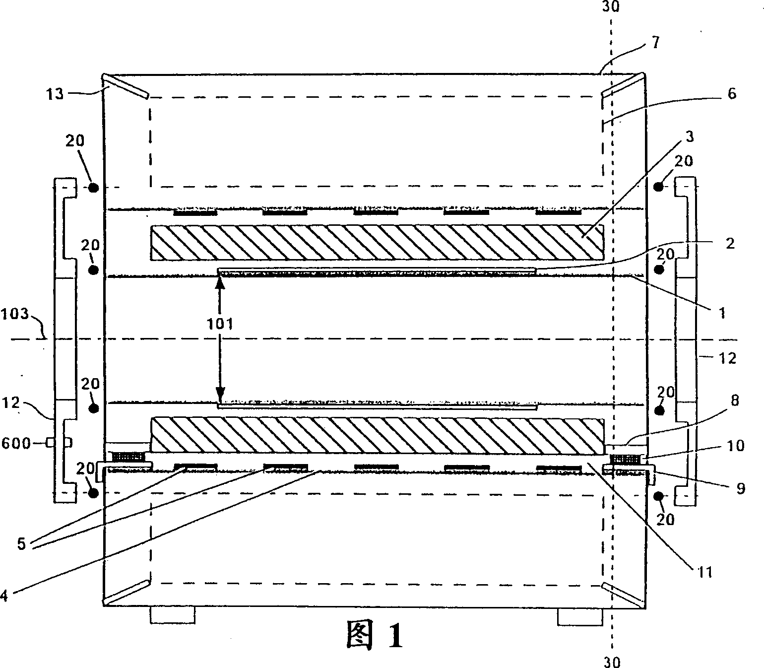
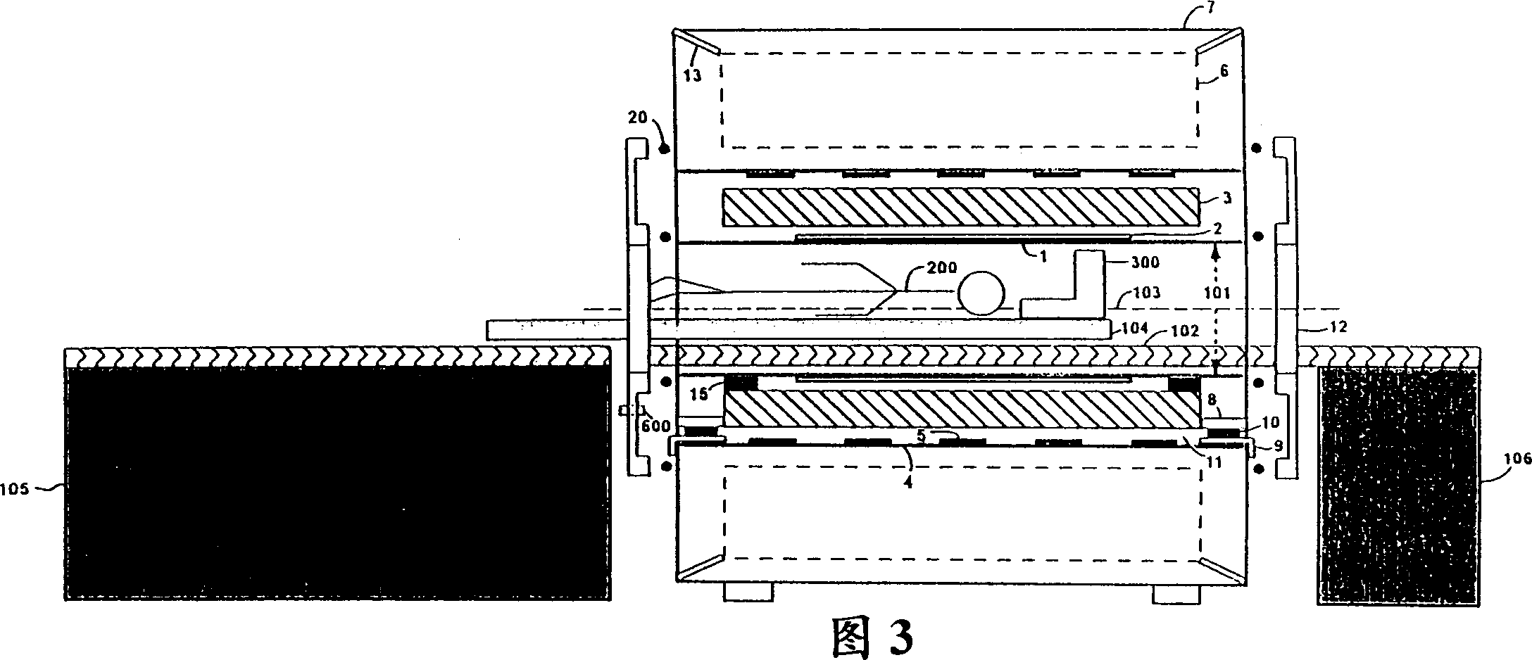
[0020] Referring to Figures 1 and 2 and 3, there is shown an exemplary imaging apparatus of a preferred embodiment of the present invention. The imaging device is of a class useful for generating magnetic resonance (MR) images of a patient or subject. Throughout the drawings, all like numerals refer to like components. Figures 1, 2 and 3 show MR systems based on cylindrical superconducting magnets. It should be clear to those skilled in the art that the functions and descriptions of similar components used in the open magnet configuration also apply to the open magnet MR system.

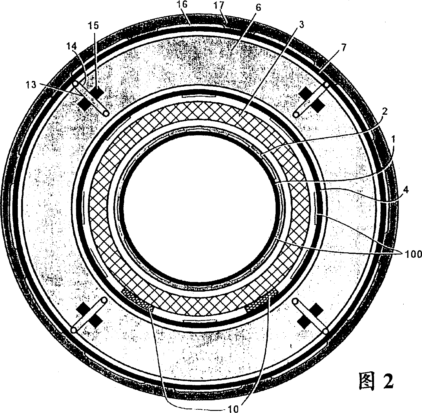
[0021] Referring to FIG. 2 , shown is a cross-sectional view of a magnet arrangement commonly associated with MR imaging. The shape of the magnet assembly is generally cylindrical and annular, and it includes an inner surface called the magnet body cavity 4, a passive magnet shim 5 (also shown in Figure 1), a magnet container 6, and radially surrounding the outer surface. Low temperature enclosure...


PUM

PropertyMeasurementUnit
Outer diameteraaaaaaaaaa

Abstract

A low noise imaging apparatus for producing Magnetic Resonance (MR) images of a subject (200) and for substantially minimizing acoustic noise generated during imaging is provided. The imaging apparatus comprises a magnet assembly (4,6,7), a gradient coil assembly (3), and a RF coil assembly (2), wherein at least one of the magnet assembly, the gradient coil assembly and the RF coil assembly are configured to reduce the generation and transmission of acoustic noise.

Description

technical field [0001] The present invention relates generally to magnetic resonance imaging (MRI) scanning devices, and more particularly, to low noise MRI scanning devices. Background technique [0002] Magnetic resonance imaging scanning devices, used in various fields (such as medical diagnosis), which generally use a computer to create images based on the operation of magnet and gradient coil assemblies and radio frequency coils. The magnet establishes a uniform primary magnetic field that generates atomic nuclei (such as hydrogen nuclei) in response to radio frequency excitation. The gradient coil assembly applies a series of pulse-excited magnetic fields with spatial gradients to the main magnetic field, so that each point in the imaging space corresponding to its unique magnetic field group has spatial consistency in the imaging pulse sequence. The RF coil creates excitation frequency pulses that temporarily create a transverse oscillatory excitation that is detecta...

Claims


Application Information

Patent Timeline
IPC IPC(8): G01R33/28A61B5/055G01R33/36G01R33/385G01R33/3873H01F5/00H01F7/20
CPCG01R33/3854A61B5/055
Inventor W·A·埃德尔斯坦R·P·马洛兹R·A·海登S·A·埃尔-哈马姆斯M·L·米勒P·S·汤普森R·A·阿克曼B·C·阿姆J·P·福拉M·J·拉齐翁D·E·德安S·T·曼赛尔D·A·普吉尔R·M·瓦雷克
Owner GENERAL ELECTRIC CO
Why Eureka
Try Eureka