Laser welding system

A technology of laser welding and hinge joint, which is applied in the direction of laser welding equipment, welding equipment, welding/welding/cutting items, etc.

Inactive Publication Date: 2002-04-24
SUNG WOO HITECH
View PDF0 Cites 6 Cited by
  • Summary
  • Abstract
  • Description
  • Claims
  • Application Information

AI Technical Summary

Problems solved by technology

[0009] The present invention has been created to solve the above-mentioned problems, and accordingly, it is an object of the present invention to provide a laser welding system in which when welding special blanks used in industrial structures by clamping The gap between the joint surface of the element and the anvil is basically overlapped, so that the joint surface of the joint part becomes stable

Method used


Image

  • Laser welding system
  • Laser welding system
  • Laser welding system

Examples


Embodiment Construction

[0030] Hereinafter, preferred embodiments of the present invention will be explained in detail by referring to the accompanying drawings.

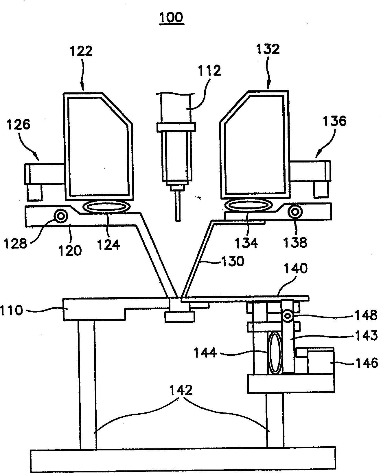
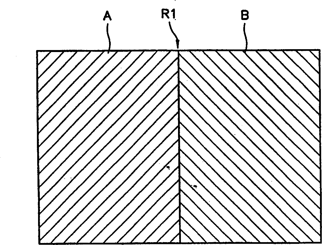
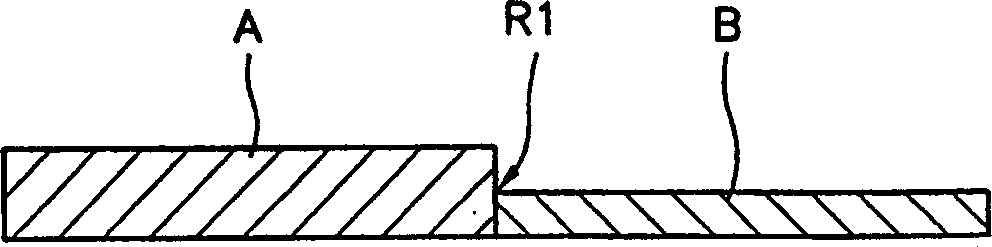
[0031] figure 1 It is a side view of a laser welding system based on the preferred embodiment of the present invention. figure 2 and image 3 respectively figure 1 Side and top views of a welded entity fabricated by the laser welding system shown in .

[0032] see figure 1 , the laser welding system according to the present invention includes a welding frame 110 , a first clamping element 120 , a second clamping element 130 , an anvil 140 and a laser welding head 112 .

[0033] The first steel plate A to be welded is placed on the welding frame. The first clamping member fixes the first steel plate A placed on the welding frame 110 , and the first clamping member is installed on the welding frame 110 .

[0034] At least one second clamping element 130 is also installed for fixing the second steel plate B to be welded near the positi...


PUM


Abstract

The laser welding system comprising a welding frame for receiving a first steel plate to be welded thereupon, at least one first clamping member installed above the welding frame, for fixing the first steel plate received on the welding frame, at least one second clamping member for fixing a second steel plate to be welded in close vicinity to a position at which the first steel plate is to be engaged with and welded with the second steel plate, an anvil on which the second steel plate is received, for moving the second steel plate to the position at which the first steel plate is to be engaged with and welded with the second steel plate, and a laser welding head for welding the first and second steel plates at the position at which the first steel plate is to be welded with the second steel plate. The first and second clamping members and the anvil are operated by air bags. The portions of the first and second members have saw-teeth, while a portion of the anvil has saw-teeth.

Description

technical field [0001] The present invention relates to a laser welding system, and more particularly to such a laser welding system, wherein when welding special blanks used in industrial construction, by operating the base of the clamping element and anvil The gap between the joint surfaces is minimized, and the joint surface of the joint part becomes stable. Thus, since the welding can be performed quickly and easily, the quality of the welded part is improved, the reliability of the structure is enhanced, and the production line of the equipment is simplified, thereby reducing the manufacturing cost of the welded entity and shortening the welding time. Background technique [0002] Special blanks are components produced by butt welding two steel plates of different thicknesses by laser welding. Special blanks are molded into shape by compression or rolling devices and are used for car bodies, doors and bumpers. So special blanks need to be of high quality and need to b...

Claims


Application Information

Patent Timeline
Patent Type & Authority Applications(China)
IPC IPC(8): B23K26/02B23K26/21B23K26/26
CPCB23K2203/04B23K26/26B23K2201/185B23K2101/185B23K2103/04
Inventor 徐廷李济熏金正五韩裕熙
Owner SUNG WOO HITECH
Why Eureka
Try Eureka