Printer system

A technology of printing system and printing head, which is applied in the field of printing system and can solve problems such as long time

Inactive Publication Date: 2002-04-24
COPYER
View PDF0 Cites 5 Cited by
  • Summary
  • Abstract
  • Description
  • Claims
  • Application Information

AI Technical Summary

Problems solved by technology

However, this method causes another problem, that is, the time required for printing in this way is too long

Method used


Image

  • Printer system
  • Printer system
  • Printer system

Examples


Embodiment Construction

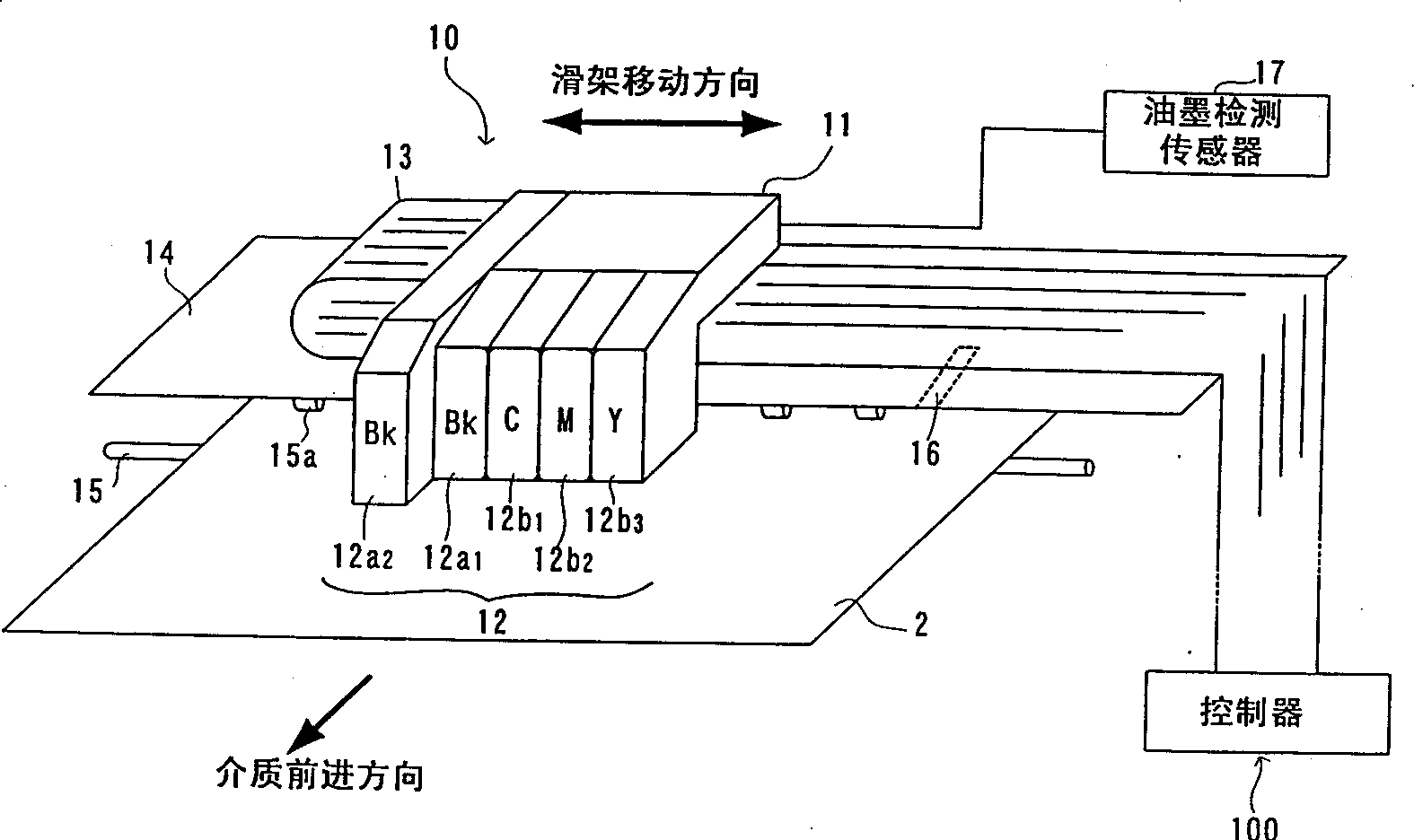
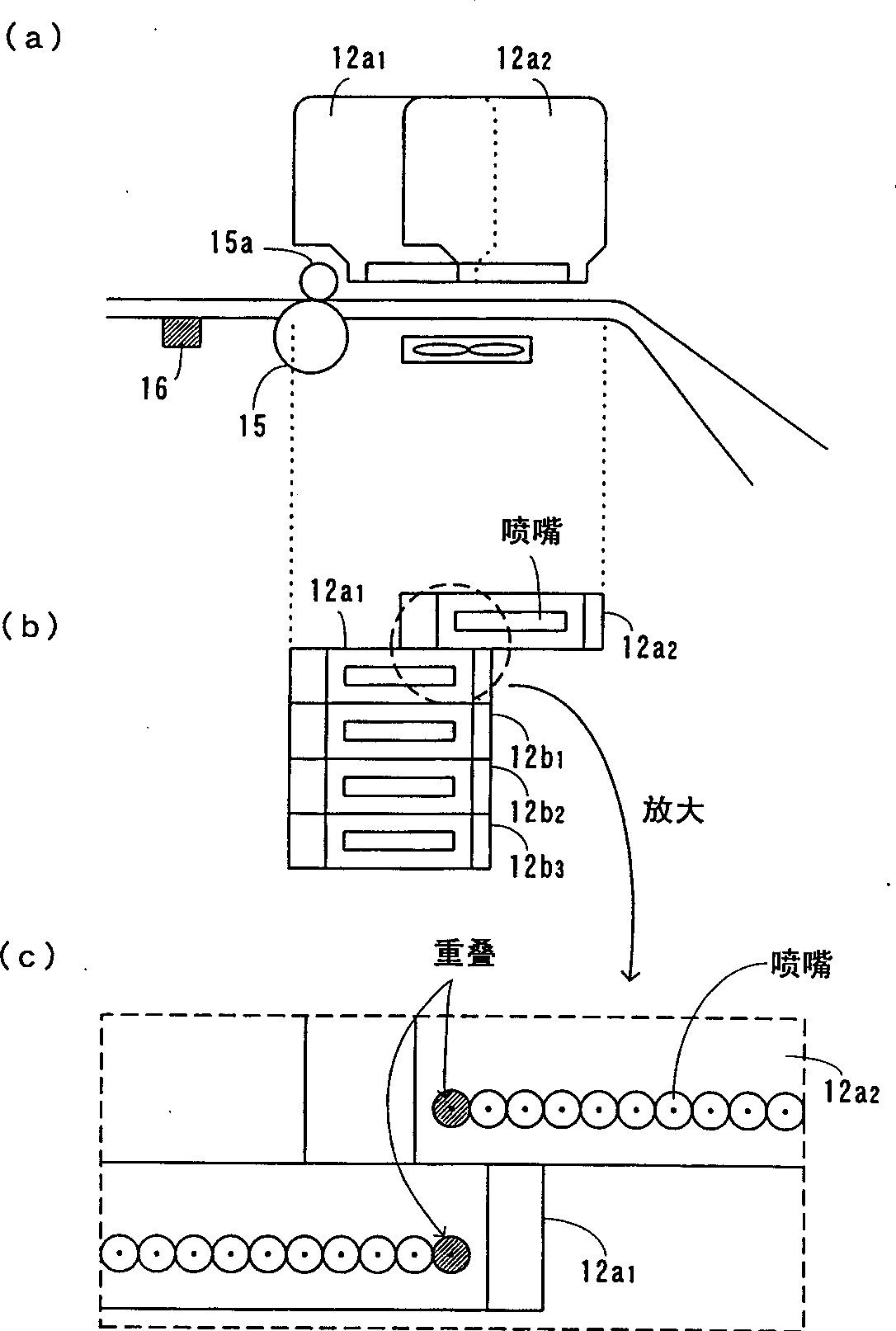
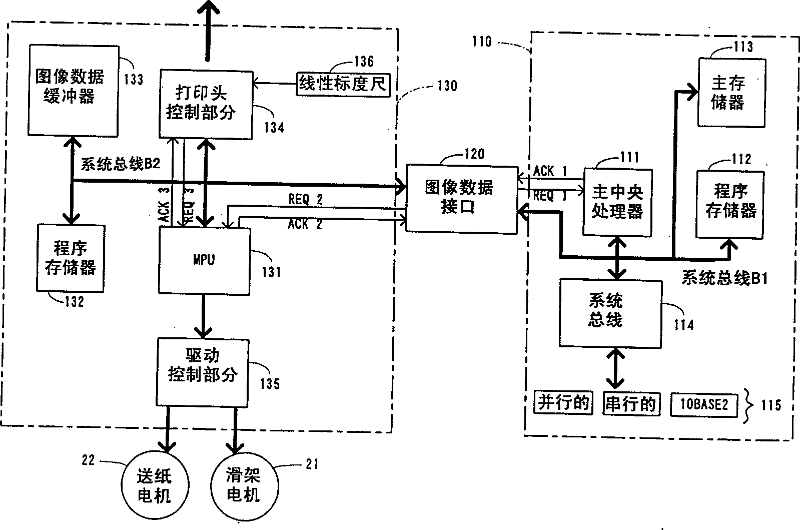
[0015] The best embodiments for carrying out the invention disclosed in this specification will be described with reference to the accompanying drawings. figure 1 is a schematic perspective view of a printing device of the printing system, which shows an embodiment of the present invention. figure 2 (a) is a schematic side view of the printhead portion of the printing system; figure 2 (b) is a schematic bottom view of the same printhead portion; and figure 2 (c) is figure 2 (b) A schematic view of a partially enlarged portion of the printhead shown. image 3 is a schematic diagram of the controller of the printing system in this embodiment.

[0016] The printing system of this embodiment includes such as figure 1 A printing device 10 and a controller 100 are shown. The envisaged printing system is a large format printer based on foam jet printing, as described below. The printing device 10 includes a carriage 11 , a print head portion 12 , a flexible flat cable (FFC)...


PUM


Abstract

A first black print head (12a1) and color print heads (12b1 - 12b3) are aligned in the direction a carriage moves. A second black print head (12a2) is deviated in the paper feed direction from the first black print head (12a1) and color print heads (12b1 - 12b3). Color image data are printed by the second black print head (12a2) and the color print heads (12b1 - 12b3). As a result, adjacent black and color dots are simultaneously printed less frequently, thus reducing smears. Black and white image data are printed by the two black heads (12a1, 12a2) at higher speed.

Description

technical field [0001] The invention relates to printing systems such as printers or plotters, especially printing systems equipped with a plurality of print heads suitable for color printing. Background technique [0002] Typically, a printing system such as a bubble jet based large printer or plotter includes multiple print heads for color printing. A plurality of print heads are arranged in parallel along the direction in which the carriage moves, and these print heads contain their respective inks, for example, made of black (Bk), cyan (C), red (M) and yellow (Y) inks. Composed of 4 colored inks. Each print head moves with the carriage, and while moving, through the nozzle, according to the specified timing, according to the given image data, eject their respective inks, so that the image with the same width as the nozzle width of a print head image, printed on the print media. [0003] The needs that color printing had to satisfy were more complex than a cursory glan...

Claims


Application Information

Patent Timeline
Patent Type & Authority Applications(China)
IPC IPC(8): B41J2/21
CPCB41J2/2103
Inventor 杉山裕一
Owner COPYER
Why Eureka
Try Eureka