Fuel line assembly and method for operating a fuel line assembly

Inactive Publication Date: 2015-06-18
TI AUTOMOTIVE HEIDELBERG
View PDF6 Cites 0 Cited by
  • Summary
  • Abstract
  • Description
  • Claims
  • Application Information

AI Technical Summary

Benefits of technology

This patent describes an invention that can minimize the problem of contaminants in fuel lines of vehicles. The invention doesn't affect the operation of the motor vehicle or the fuel supply system. It can be easily and cost-effectively implemented to remove contaminant particles during manufacturing of the fuel line assembly. The invention can prevent damage to vehicle components caused by contaminants and allows for effective protection against contamination. Overall, the invention provides a simple and effective solution to the problem of fuel line contamination.

Problems solved by technology

These contaminant particles, or dust particles, respectively, can compromise, and in particular clog or block, the operation of the fuel line assembly, or the components connected to the motor vehicle allocated thereto, respectively, such as the nozzles, injectors, pumps or filter.
This is complex and expensive, however.
Furthermore, frequently not all of the contaminants can be eliminated, or removed, however, such that during operation of the fuel line assembly, undesired disruptions may nevertheless occur.

Method used


Image

  • Fuel line assembly and method for operating a fuel line assembly
  • Fuel line assembly and method for operating a fuel line assembly
  • Fuel line assembly and method for operating a fuel line assembly

Examples


Embodiment Construction

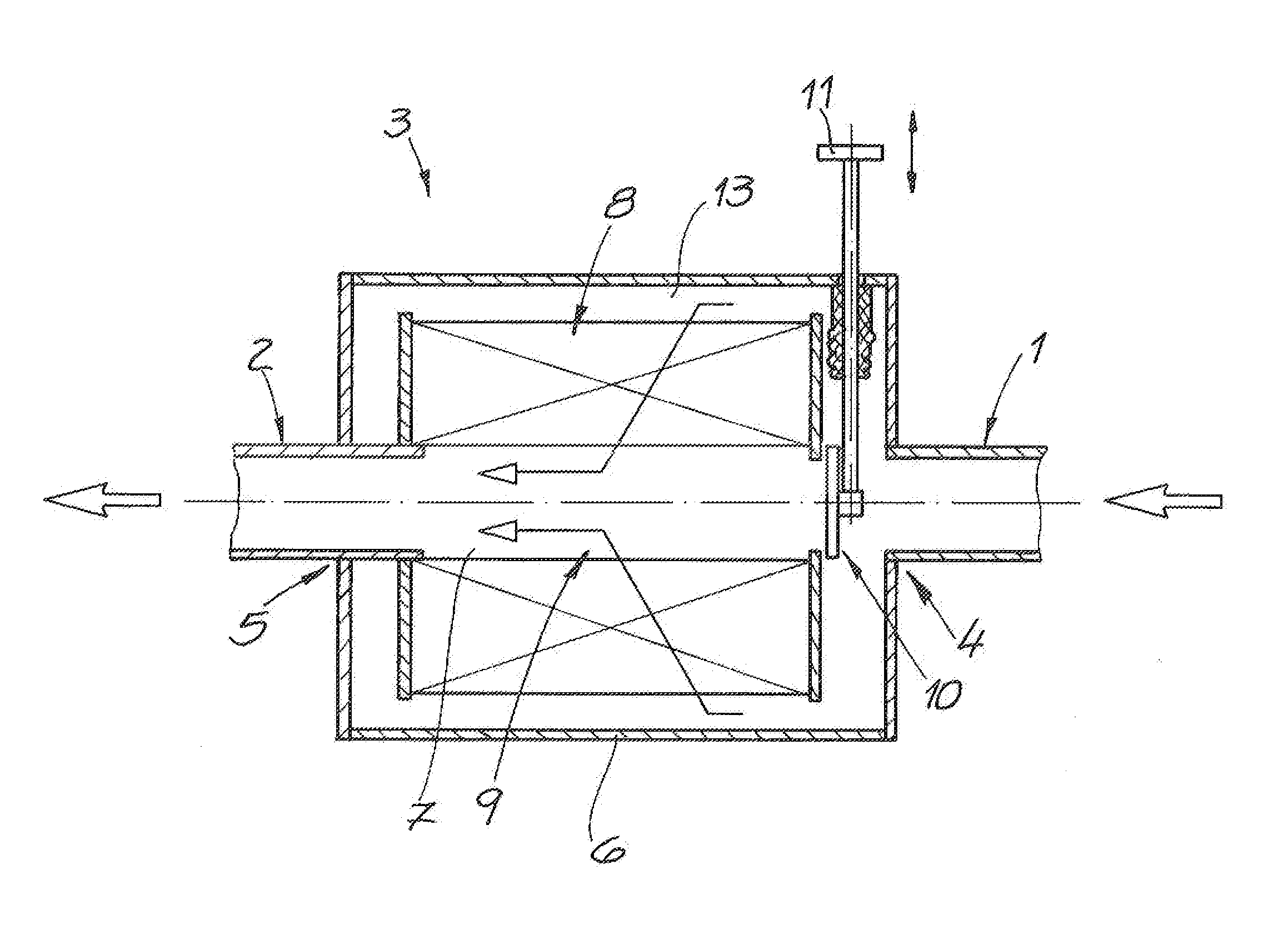
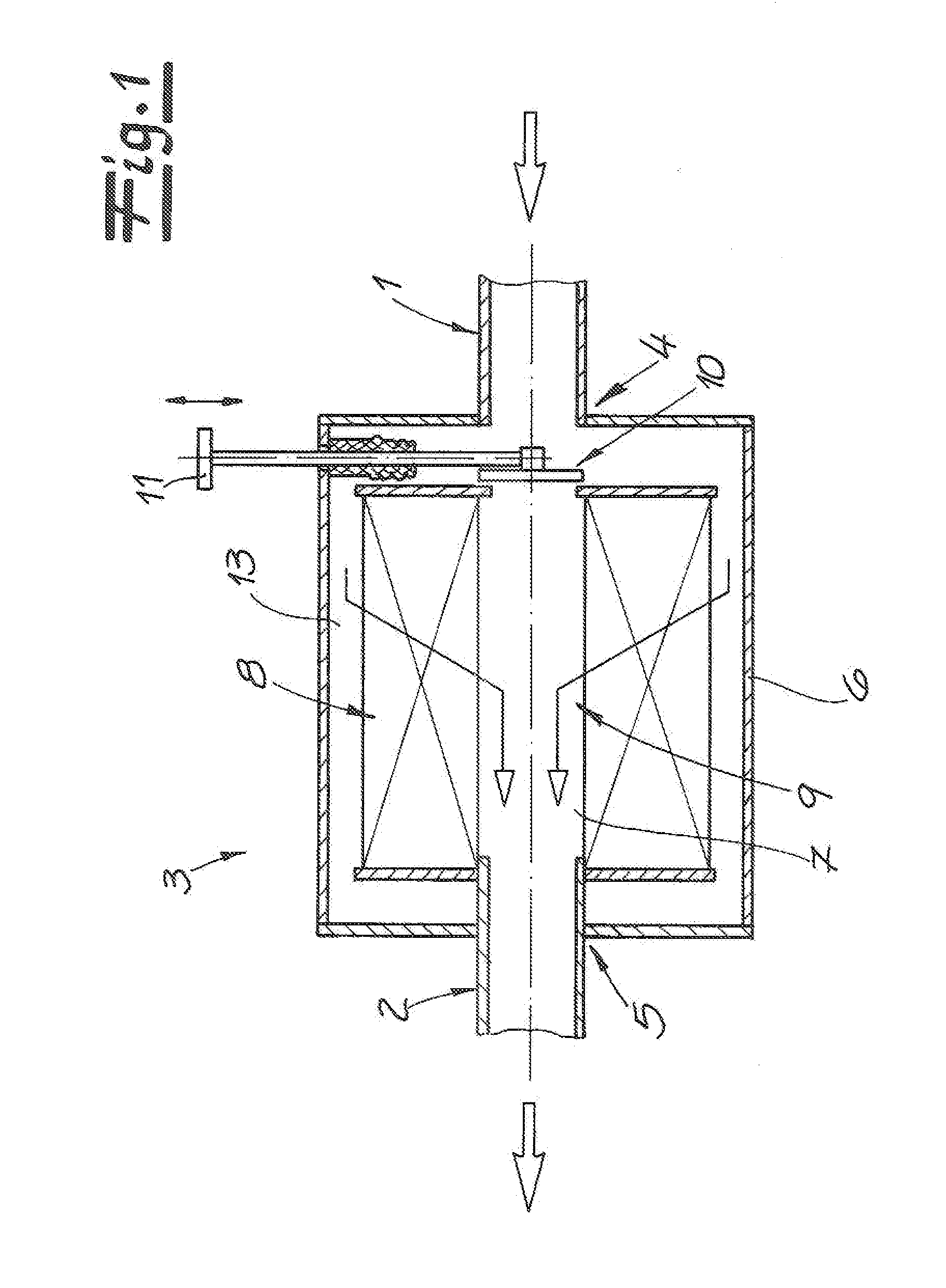
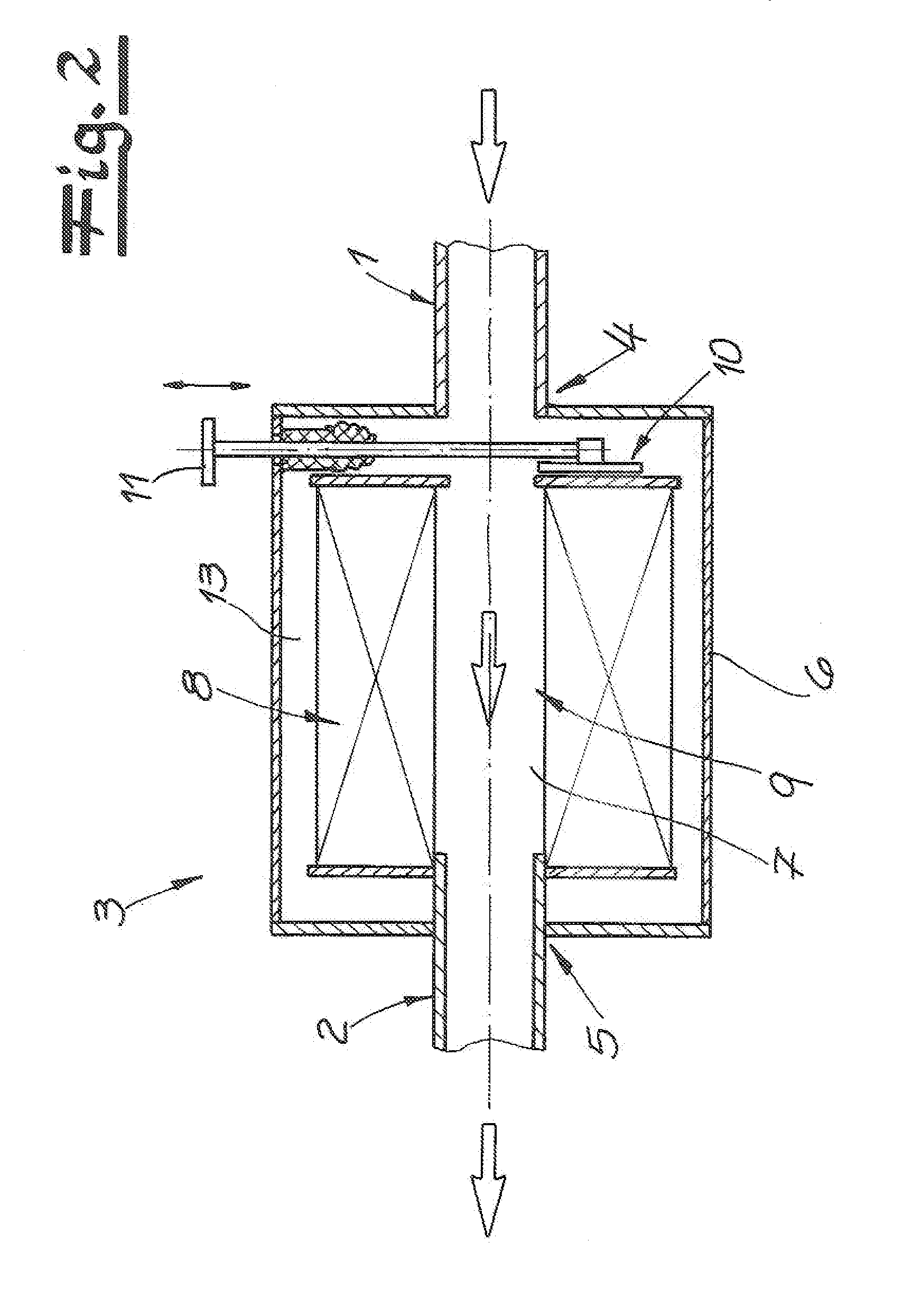
[0023]The figures show an inventive fuel line assembly for motor vehicles, which are not depicted in greater detail, in particular motor vehicles with diesel engines. The fuel line assembly has two tubing sections 1, 2 and one filter device 3 disposed between the tubing sections 1, 2. A first tubing section 1 is connected to an intake end 4 of the filter device 3, and a second tubing section is connected to a discharge end 5 of the filter device. The tubing sections 1, 2 consist, for practical purposes, of plastic, and preferably have a circular cross-section.

[0024]The filter device 3 that connects the tubing sections 1, 2 preferably, and in the embodiment, has a cylindrical filter housing 6.

[0025]It is recommended that, and in the embodiment example, an outlet channel 7 for the fluid medium, or for the fuel, respectively, runs through the middle, or center, respectively, of the filter housing 6. Preferably, and in the embodiment example, the outlet channel 7 has the same flow cross...


PUM


Abstract

A fuel line assembly for motor vehicles, having two tubing sections and at least one filter device disposed between the two tubing sections. Fuel is supplied to the filter device via a first tubing section, and fuel is discharged from the filter device via a second tubing section, wherein the filter device has two functional states. In a first functional state of the filter device, the fuel supplied thereto is filtered by means of at least one filter medium in the filter device. After a blocking element in the filter device has been switched to a second functional state, the fuel flows through the filter device via at least one outlet channel, without filtering.

Description

CROSS-REFERENCE TO RELATED APPLICATIONS[0001]This application claims priority pursuant to Title 35 U.S.C. §119(e) to European application for Patent No. 13 197 668.0, filed Dec. 17, 2013 for Fuel Line Assembly and Method for Operating a Fuel Line Assembly.BACKGROUND[0002]The invention relates to a fuel line assembly for motor vehicles, having a plurality of tubing sections. The invention relates in particular to a fuel line assembly for diesel fuel, or for diesel engines, respectively. The invention furthermore relates to a method for operating a fuel line assembly.[0003]Fuel line assemblies for motor vehicles are known in the field in various embodiments. During the manufacturing of the fuel line assembly, or the tubing sections of these assemblies, respectively, contaminant particles such as dust particles and the like are produced. These contaminant particles, or dust particles, respectively, can compromise, and in particular clog or block, the operation of the fuel line assembly...

Claims


Application Information

Patent Timeline
IPC IPC(8): F02M37/22F02M37/00F02M37/36
CPCF02M37/22F02M37/0017F02M37/007Y10T137/0318Y10T137/794F02M37/36
Inventor JENSEN, HANS
Owner TI AUTOMOTIVE HEIDELBERG
Why Eureka
Try Eureka