Eureka AIR delivers breakthrough ideas for toughest innovation challenges, trusted by R&D personnel around the world.

Dynamic serializing of memory access in multiprocessor system

A memory and shared memory technology, applied in memory systems, electrical digital data processing, instruments, etc., can solve problems such as communication and delay increase

Inactive Publication Date: 2002-05-01
IBM CORP
View PDF0 Cites 19 Cited by
  • Summary
  • Abstract
  • Description
  • Claims
  • Application Information

AI Technical Summary

Problems solved by technology

After each one is completed, the priority mechanism is tested again, and the busyness of resources will lead to increased communication and delay

Method used


Image

  • Dynamic serializing of memory access in multiprocessor system
  • Dynamic serializing of memory access in multiprocessor system
  • Dynamic serializing of memory access in multiprocessor system

Examples


Embodiment Construction

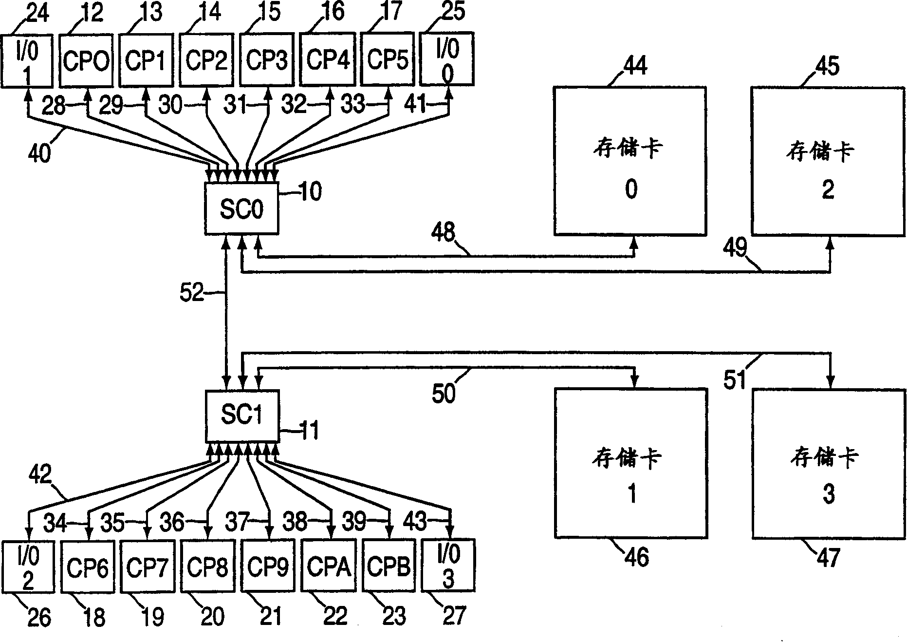
[0010] figure 1 is a system overview of the multiprocessor system of the preferred embodiment;

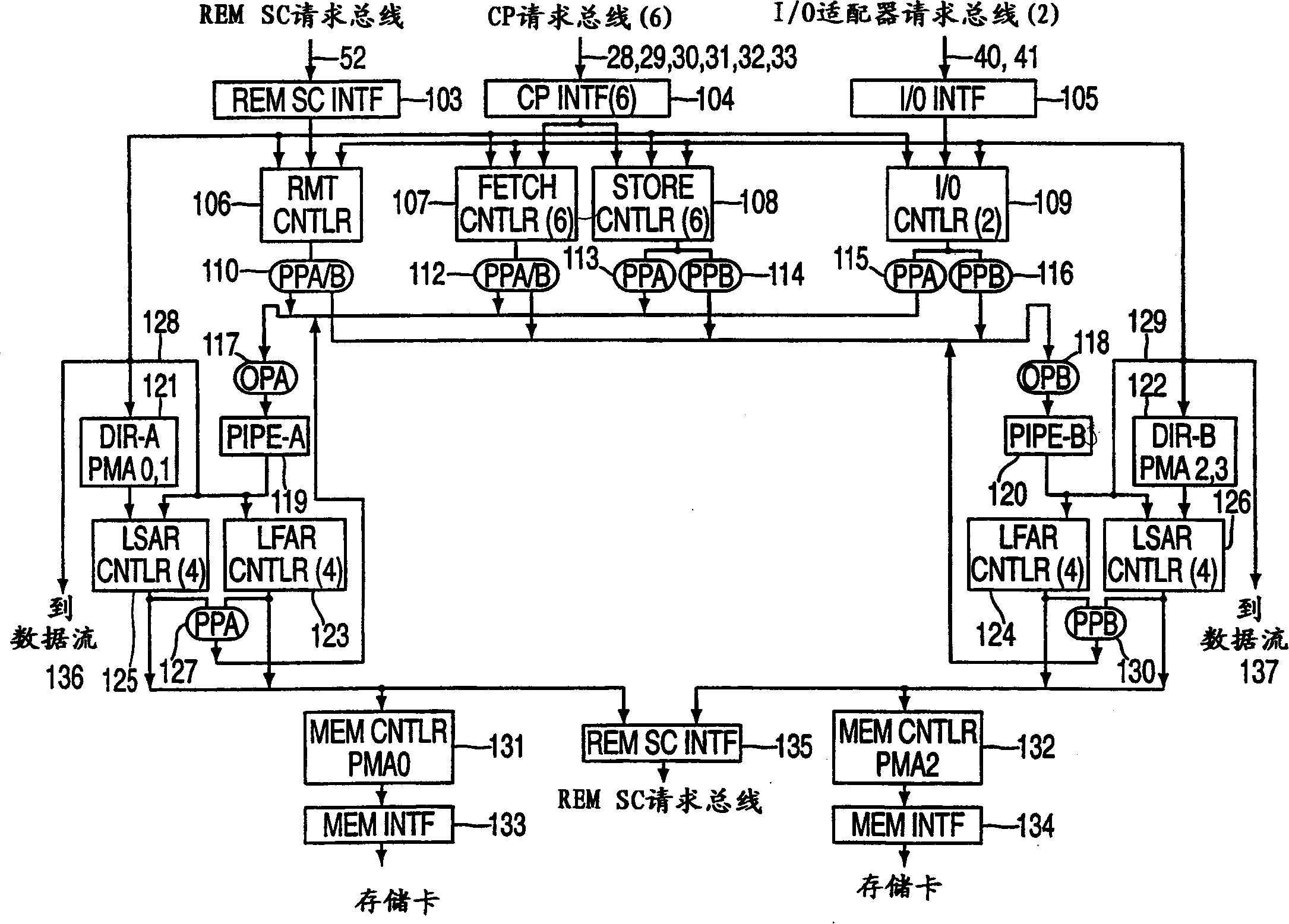
[0011] figure 2 is in figure 1A block diagram of the address flow of a single memory controller in a multiprocessor system;

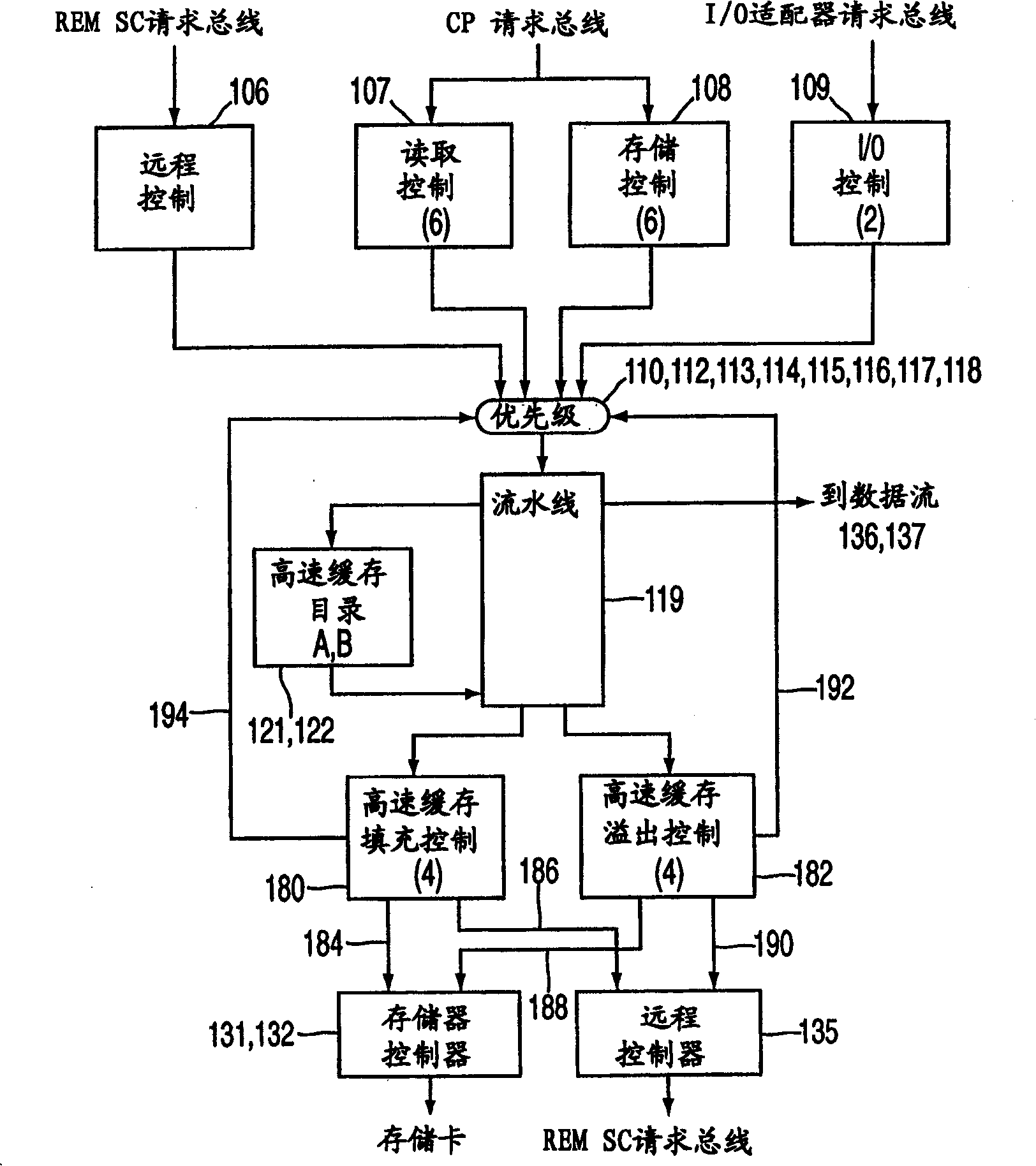
[0012] image 3 is a generalized diagram of the system overview of the optimal multiprocessor system;

[0013] 4 is a block diagram of a plurality of CPU read controllers that generate requests to the CPU read pre-priority stations;

[0014] Figure 5 is a block diagram of an encoder that creates a comparison identifier for the requester corresponding to the pipeline identifier;

[0015] Figure 6 is a block diagram of addresses maintained by a read controller and the manner in which the read controller provides address comparison;

[0016] Figure 6A is a block diagram of a pipeline supervisor;

[0017] Figure 7 is the generation block diagram of the pending reset;

[0018] Figure 8 is a block diagram of a set of requirements registers;

[0019] ...


PUM


Abstract

A method for resolving address contention and prioritization of access to resources within a shared memory system includes dynamically creating ordered lists of requests for each contested resource. A new request is added to the lists only after a conflict is recognized. Since the resource conflict does not always exist, there is no impact to a request for an uncontested resources.

Description

technical field [0001] The present invention relates to computers and computer systems, and more particularly to mechanisms for resolving address conflicts and resource access priorities within a shared memory system. Background technique [0002] Multiprocessor systems can take many forms, and individual solutions may contain many unique characteristics. Common among multiprocessor systems is the need to resolve shared address conflicts. A shared address conflict occurs when one or more processors attempt to update shared data. Since resolving such conflicts requires a serialized access, system designers avoid situations where this behavior occurs. For example, a processing unit may be assigned a dedicated address space by the operating system; enabling the processor to work without conflicting constraints. Even in this environment, an idle processor will usually get new jobs from a queue held in a shared address space. As the speed and number of processors increase, th...

Claims


Application Information

Patent Timeline
Patent Type & Authority Applications(China)
IPC IPC(8): G06F15/177G06F12/00G06F12/08G06F13/16
CPCG06F12/084G06F13/1663G06F12/0828
Inventor M·菲P·K·马克
Owner IBM CORP
Why Eureka
Eureka Blog
Learn More