Belt for non-stage transmissions

A speed changer and transmission belt technology, applied in V-shaped belts, mechanical equipment, belts/chains/gears, etc., can solve the problems of reduced durability, uneven contact, and partial wear of metal components

Inactive Publication Date: 2002-05-01
HONDA MOTOR CO LTD
View PDF2 Cites 9 Cited by
  • Summary
  • Abstract
  • Description
  • Claims
  • Application Information

AI Technical Summary

Problems solved by technology

[0003] However, in the above-mentioned prior art, when the V-shaped surface of the metal element is subjected to the compressive load from the V-shaped groove of the pulley, the V-shaped surface does not move in parallel but moves at a variable angle, so that the upper or lower part of the V-shaped surface is not uniform. Butting against the V-shaped groove of the pulley

Method used


Image

  • Belt for non-stage transmissions
  • Belt for non-stage transmissions
  • Belt for non-stage transmissions

Examples


Embodiment Construction

[0010] Embodiments of the present invention will be described below with reference to the embodiments of the present invention shown in the accompanying drawings.

[0011] Figures 1 to 10B An embodiment of the present invention is shown.

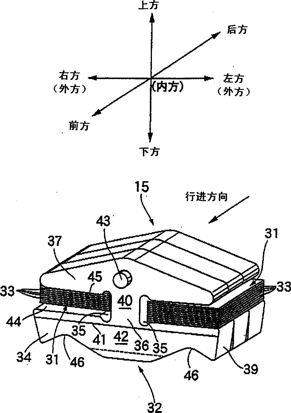
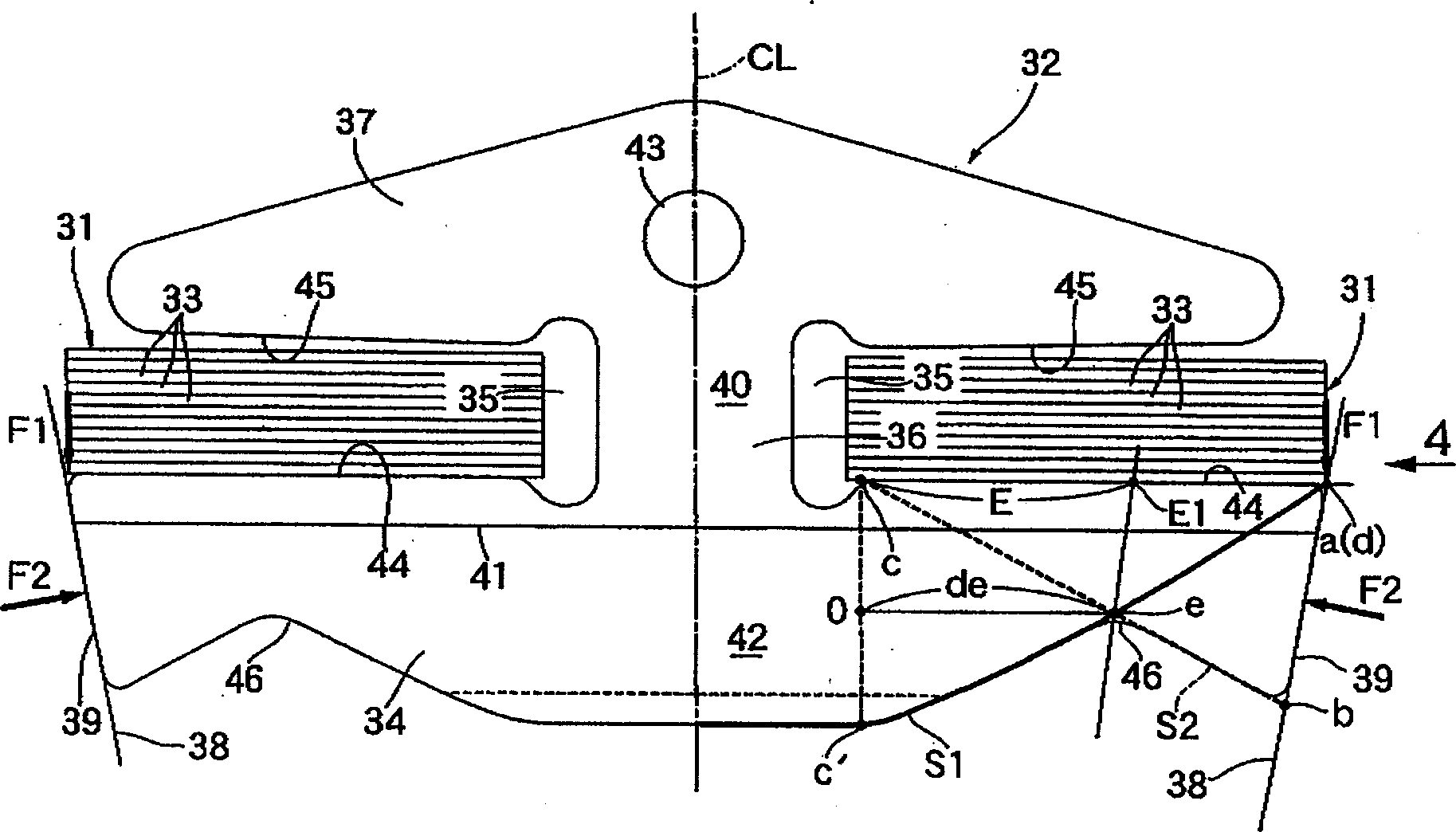
[0012] In addition, the definitions of the front-rear direction, the left-right direction, the up-down direction, and the inner-outer direction of the metal element used in this embodiment are as follows: figure 2 shown.

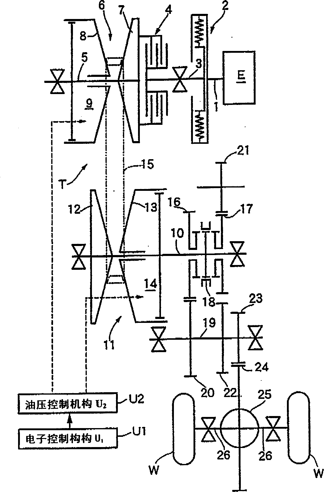
[0013] figure 1 The schematic structure of a metal belt continuously variable transmission T mounted on an automobile is shown. The input shaft 3 connected to the crankshaft 1 of the engine E via the shock absorber 2 is connected to the drive shaft 5 of the metal belt type continuously variable transmission T via the starting clutch 4 . The drive pulley 6 provided on the drive shaft 5 includes a fixed-side pulley half body 7 fixed to the drive shaft 5 , and a movable-side pulley half body 8 that is attachable to and ...


PUM


Abstract

In a belt for a continuously variable transmission, a first line on a lower edge of an element body of a metal element is determined, and a second line straightforwardly connecting a lower end of a V-face to which a load is applied from a V-groove in a pulley and an inner end of a saddle surface is determined, so that when a downward load is applied from a metal ring assembly to an outer end of the saddle surface, the folding-resistant strength of the element body is uniform laterally. The position of the recess is determined in the vicinity of a point of intersection of the first and second lines. The lower edge of the element body is defined by the first line inside the recess and by the second line outside the recess. The durability of the metal element can be enhanced by devising the shape of the lower edge of the element body of the metal element in this manner.

Description

technical field [0001] The present invention relates to a pair of left and right ring grooves formed in a plurality of metal elements, respectively supported by a pair of left and right metal ring aggregates formed by laminating a plurality of annular metal rings, and is wound around a driving pulley and a driven pulley. A continuously variable transmission belt that transmits drive power. Background technique [0002] In such a continuously variable transmission belt, in order to press the left and right V-shaped surfaces of the metal element to the V-shaped grooves of the pulley with a uniform surface to prevent uneven wear, the left and right V-shaped surfaces near the lower edge of the main body of the element are placed on the left and right sides of the V-shaped surface. The end portion is formed with an upward concave portion, so that the element body portion is easily bent up and down at the position of the aforementioned concave portion. This technique is known fro...

Claims


Application Information

Patent Timeline
IPC IPC(8): F16G5/16
CPCF16G5/16
Inventor 鹿子木健吉田秀昭
Owner HONDA MOTOR CO LTD
Why Eureka
Try Eureka