

Powder metallurgy material and friction body and friction disc applied by same
A powder metallurgy, friction body technology, applied in friction linings, mechanical equipment, gear shifting mechanisms, etc., can solve the problems of short service life and poor temperature resistance of friction discs, and achieve extended service life, good wear resistance, and guaranteed The effect of friction coefficient and service life
- Summary
- Abstract
- Description
- Claims
- Application Information
AI Technical Summary
Problems solved by technology
Method used
Image

Examples
Embodiment 1
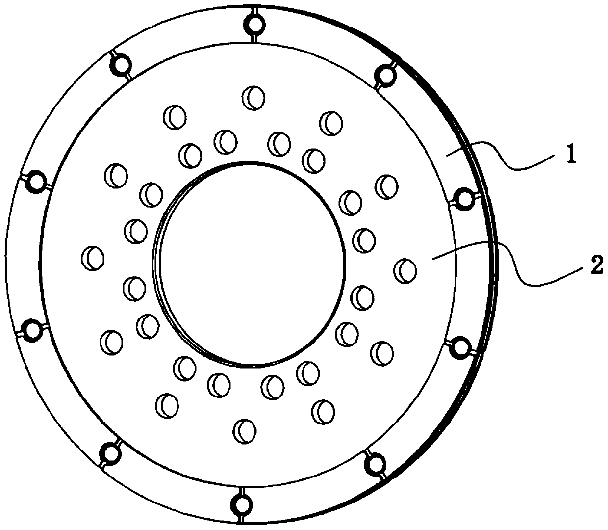
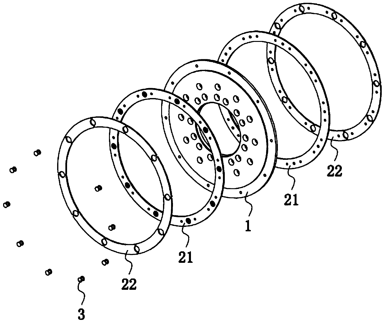
[0042] combine figure 1 and figure 2 , this embodiment relates to a friction disc, including a mounting part 1, a friction assembly 2 and a mechanical connection part 3, wherein the mounting part 1 is suitable for assembling with the main shaft of the coupling, and the mounting part 1 is mainly used for mounting and The role of supporting the entire friction disc, the friction assembly 2 is assembled with the mounting part 1, the friction assembly 2 is used for friction, and the mechanical connection part 3 is used for assembling the friction assembly 2 and the mounting part 1.
[0043] Specifically, the mounting part 1 is in the shape of a disk, and the mounting part 1 is provided with a mounting hole suitable for the main shaft of the coupling. The mounting part 1 is made of a metal material. In this embodiment, the mounting part 1 adopts 40Cr, in other embodiments, the mounting piece 1 can also be made of 45# steel.
[0044] The friction assembly 2 includes a metal botto...
Embodiment 2-8
[0062] Embodiment 2-8 relates to a friction disc, the friction disc includes: a mounting part made of 40Cr material, and a friction assembly, the friction assembly includes a metal bottom pad made of Q235B steel back and a powder metallurgy material sintered The formed friction body, wherein, the metal base pad and the mounting part are fixedly connected by rivets, and the friction assembly is prepared according to the following method:
[0063] S1. After weighing the powder metallurgy material used to prepare the friction body according to the proportion, put it into a V-shaped mixer and mix it for 8 hours until the ingredients of each material are evenly stirred. The consumption of the powder metallurgy material in each embodiment is shown in Table 1;
[0064] S2. Put the mixed raw materials into the mold, press the powder metallurgy material on the metal bottom pad under the pressure of 400MPa, and finally shape it into a friction assembly block;
[0065] S3. Place the pres...
Embodiment 9
[0071] Embodiment 9 relates to a friction disc. The difference between Embodiment 9 and Embodiment 2 is that the friction assembly is prepared according to the following method:
[0072] S1. After weighing the raw materials according to the proportion, put them into a V-shaped mixer and mix them for 6 hours until the ingredients of each material are evenly stirred. The consumption of raw materials in each embodiment is shown in Table 1;
[0073] S2. Put the mixed raw materials into the mold, press the powder metallurgy material on the metal bottom pad under the pressure of 300MPa, and finally shape it into a friction assembly block;
[0074] S3. Place the pressed friction assembly compact in a bell-type pressurized sintering furnace, raise the temperature from room temperature to 900° C. at a rate of 5° C. / min, and then keep the compact for 180 minutes to sinter the compact. The sintering process uses hydrogen as the protective atmosphere, and mechanically pressurizes the comp...
PUM
| Property | Measurement | Unit |
|---|---|---|
| hardness | aaaaa | aaaaa |
Abstract
Description
Claims
Application Information