Over filling interdiction, vent and roll over valve

A technology of flipping valves and valve seats, which is applied in safety valves, balance valves, valve devices, etc., and can solve problems such as unsuitable discharge of fuel gas and delay of sealing membranes

Inactive Publication Date: 2002-05-15
拉瓦尔农业合作社有限公司
View PDF2 Cites 19 Cited by
  • Summary
  • Abstract
  • Description
  • Claims
  • Application Information

AI Technical Summary

Problems solved by technology

[0005] In addition, the disengagement of the closing diaphragm from the valve seat may be slightly delayed, especia

Method used


Image

  • Over filling interdiction, vent and roll over valve
  • Over filling interdiction, vent and roll over valve
  • Over filling interdiction, vent and roll over valve

Examples


Embodiment Construction

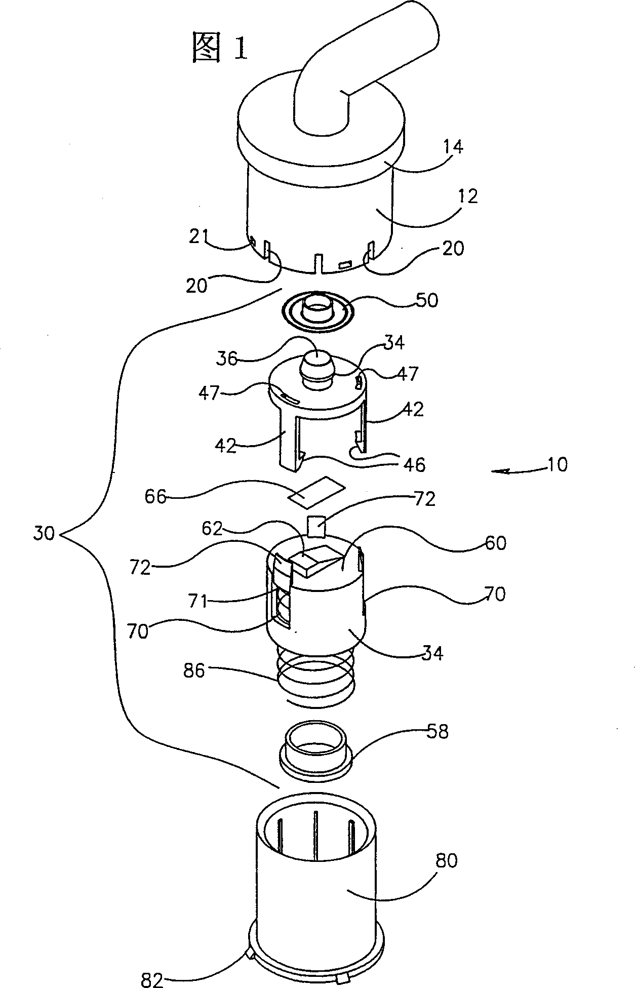
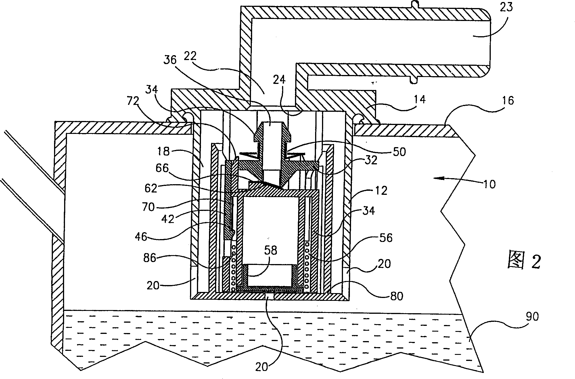
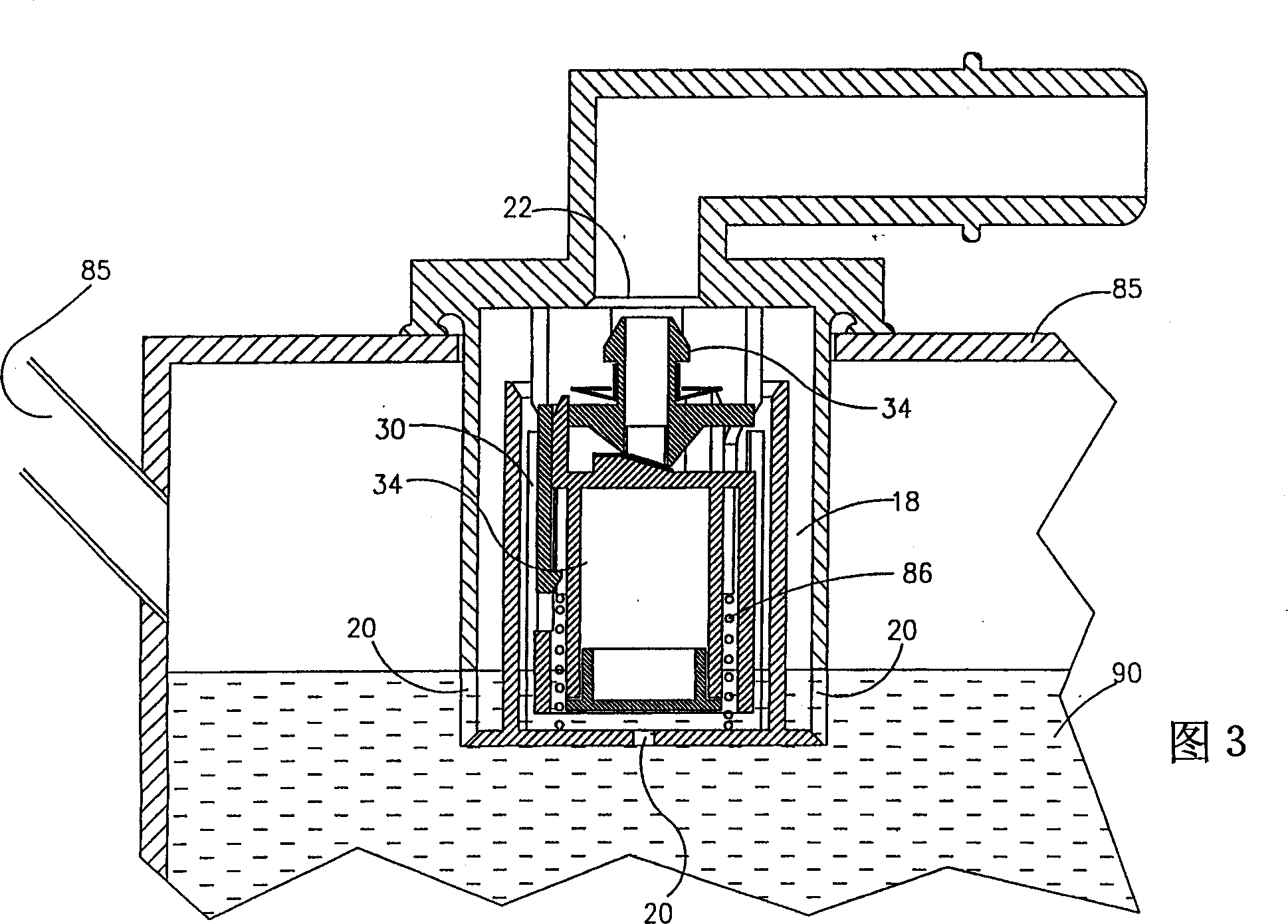
[0032] Attention is first directed to FIGS. 1 and 2 to understand the structure of the valve generally represented by numeral 10 . The valve comprises a cylindrical housing portion 12 on which a flange 14 is formed on an upper portion for being connected to an outer surface of a fuel tank 16 by heat welding; wherein the cylindrical housing portion 12 protrudes into the fuel tank 16 . A duct portion 23 is provided in flow connection with the outlet portion 22 .

[0033] As best seen in Figure 2, the housing defines an enclosed space 18 having a plurality of liquid inlets 20 and at a top of the enclosed space an outlet portion 22 defined by a valve seat 24. The housing 12 also includes a recess 21 in its lower part.

[0034] A valve assembly 30 includes a first stage 32 and a second stage 34 . The first stage 32 has a conical protrusion 34 at a top thereof, in which an outlet hole 36 is formed. The first stage 32 is formed at a bottom thereof with an elongated slit-shaped in...


PUM


Abstract

An over filling interdiction and roll over valve (10) comprising a housing (12) defining a confined space (18) formed with fluid inlets (20), a fluid outlet port (22) at a top end of the confined space (18), and a valve seating (24) bounding the outlet port (22). A valve assembly is located within the confined space and comprises a first stage member (32) and a second stage member (34), both being substantially coaxially displaceable within the housing. The first stage member has at a bottom end thereof a substantially elongated slit-like inlet aperture (36), and at a top end thereof an outlet aperture being in flow communication with the inlet aperture. The first stage member is axially displaceable between a first position in which the outlet aperture progressively sealingly engages the outlet port of the housing, and a second position in which it is disengaged therefrom. The second stage member is a float fitted with a flexible closure membrane strip (66) anchored at one end thereof to a top wall (62) of the float member. The closure membrane faces the inlet aperture of the first stage member, and the second stage member is displaceable between a first position in which the closure membrane sealingly engages the inlet aperture, and a second position in which it is progressively disengaged therefrom. At least one anchoring member (42) extending between the first stage member (32) and the second stage member (34).

Description

technical field [0001] The present invention relates generally to the field of valves, and in particular to a combination valve for use in vehicle fuel tanks of multi-purpose quality. Background technique [0002] A wide variety of valves for vehicle fuel tanks are known. For example, U.S. Patent No. 5,738,132 discloses a roll-over and relief valve (ROV) comprising a housing formed by an inlet and an outlet, the outlet comprising a slit-shaped The buoyant member is axially movable between the inlet and the outlet. An elongated closure piece is secured to the end of the housing adjacent the outlet, and a spring biases the float member in the direction of the outlet. [0003] This configuration is such that the force of the spring bias and the float acting on the float tend to press the diaphragm into sealing engagement with the outlet opening, while the force of gravity on the float tends to move the float away from the outlet. to gradually disengage the sheet from sealing...

Claims


Application Information

Patent Timeline
IPC IPC(8): B60K15/077F02M37/00F16K17/36F16K24/04
CPCF16K24/042F16K17/36Y10T137/3099Y10T137/0874B60K2015/0346B60K15/03B60K1/00B60K2015/03289
Inventor 埃胡德·奥伦斯坦祖哈尔·穆阿利姆约阿夫·利夫内弗拉迪米尔·欧尔钦斯基
Owner 拉瓦尔农业合作社有限公司
Why Eureka
Try Eureka