
Cooling system of vehicles

A cooling system and vehicle technology, applied in liquid cooling, vehicle components, engine cooling, etc., can solve the problems of fan horsepower increasing system cost, increasing operating costs, etc.

Inactive Publication Date: 2002-05-22
MODINE MFG CO
View PDF1 Cites 8 Cited by
  • Summary
  • Abstract
  • Description
  • Claims
  • Application Information

AI Technical Summary

Problems solved by technology

Excessive fan horsepower not only increases system cost, but also increases operating costs

Method used


Image

  • Cooling system of vehicles
  • Cooling system of vehicles
  • Cooling system of vehicles

Examples


Embodiment Construction

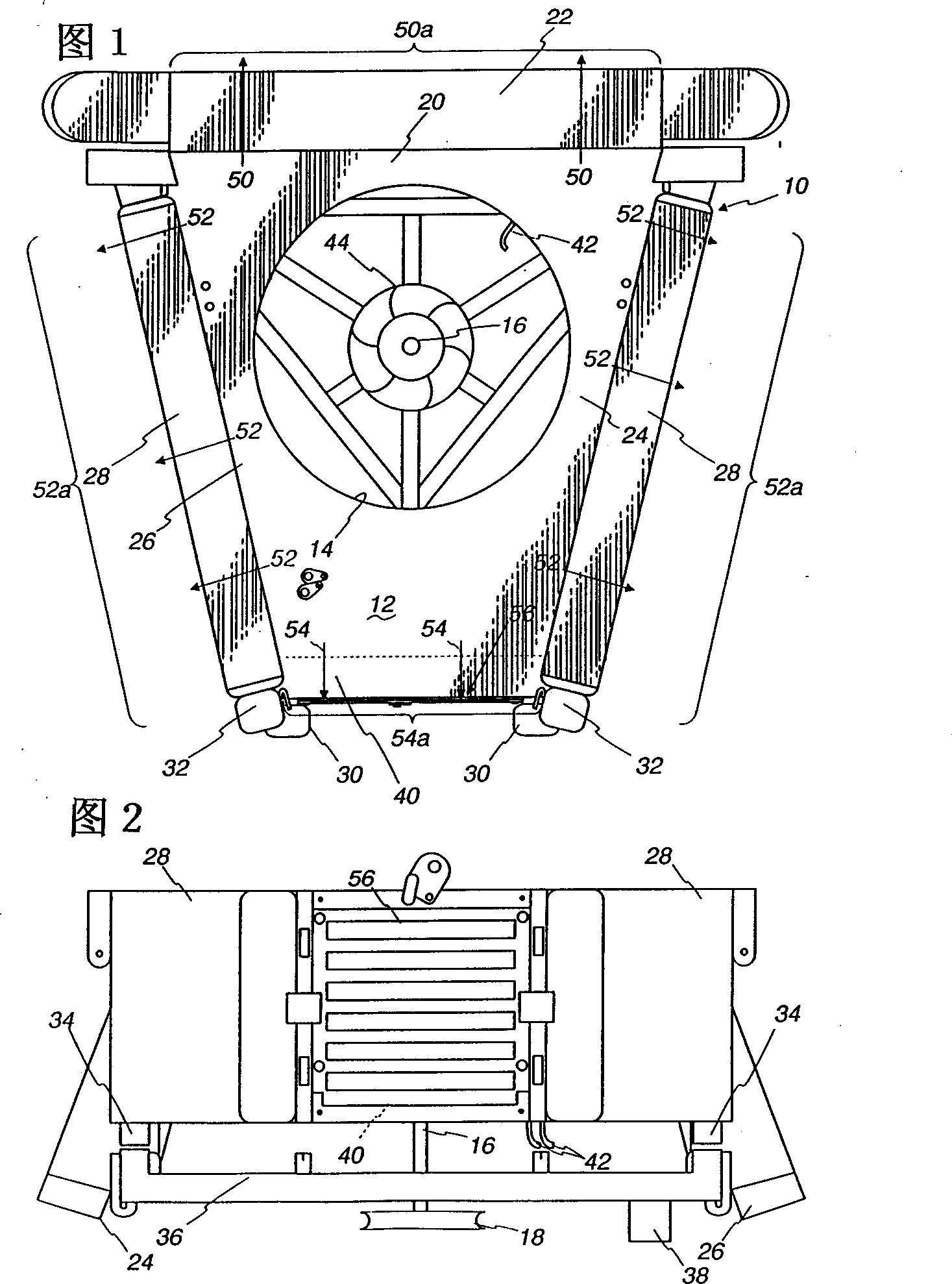
[0028] The present invention will be described in the context of cooling system assemblies using radial fans such as commonly assigned co-pending patent application serial number 09 / 194993 filed November 3, 1998 by Ehlers et al. As disclosed, this application is hereby incorporated by reference in its entirety. It should be understood, however, that the invention is not limited to use with the disclosed assemblies. In particular, Ehlers et al. disclose a so-called "compact cooling system" in which the heat exchangers are arranged radially outward from the radial fans to form a polygon. However, the invention is also useful for other cooling system components where, for example, a set of heat exchangers are arranged side-by-side substantially in a common plane, the powertrain heat exchanger being located on one side of the air cooler of an air conditioning system.

[0029] It will also be seen that although the invention has been described in connection with so-called radial f...


PUM


Abstract

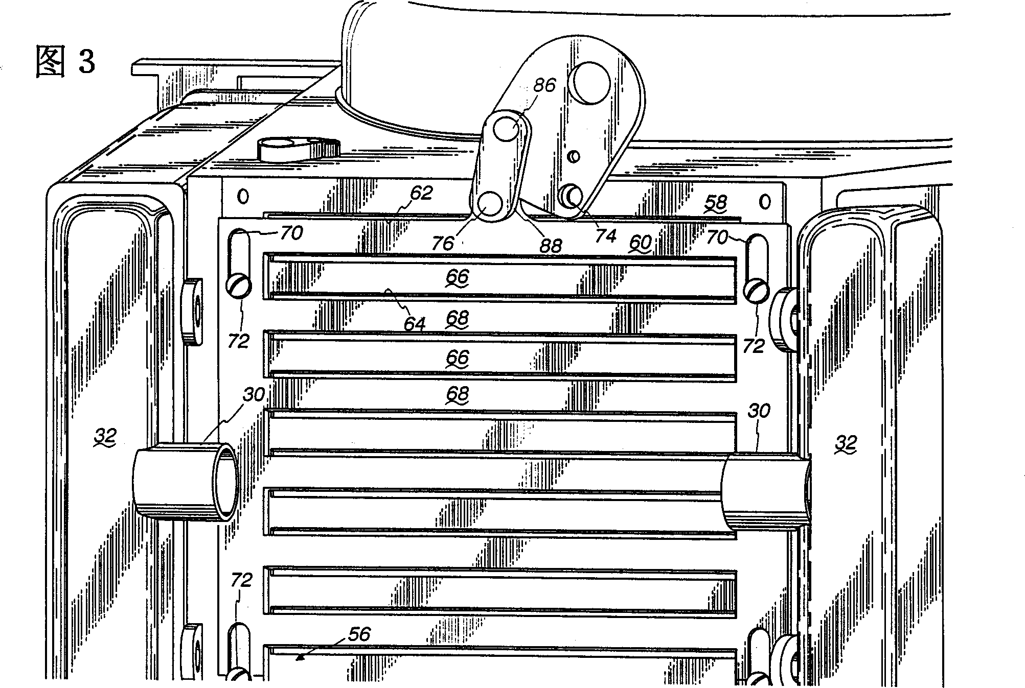
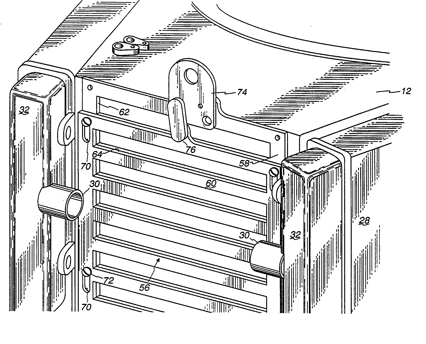
Fan horsepower requirements and the size of power train heat exchangers may be reduced in a vehicular cooling system that includes an inlet (14) for the receipt of ambient air and first and second heat exchangers (28), (40) in proximity to the inlet to receive ambient air therefrom and which are respectively adapted to receive first and second heat exchanger fluids by the ambient air. The first and second heat exchangers are in side by side, substantially non superimposed relation to define first and second air flow paths (52, 54) extending in fluid flow parallel to a respective one of the heat exchangers from the inlet to points (50), (52), (54) of discharge. A fan (44) flows air from the inlet through the flow paths and a shutter (56) is located in one of the flow paths (54) and is movable between first and second positions respectively restricting air flow and allowing relatively unrestricted air flow. An actuator (88) provided for moving the shutter (56) between the positions and a control (90, 98, 100) is provided for the actuator (88) which is responsive to power train and air conditioning system operating conditions.

Description

technical field [0001] The present invention relates to vehicle cooling systems, and more particularly, to a vehicle cooling system that reduces fuel consumption and provides greater tractive effort. Background technique [0002] Vehicle cooling systems are becoming increasingly complex. Cooling systems on early internal combustion engine powered vehicles were as simple as a fin arrangement outside the engine cylinders to provide air cooling to the engine, but have come a long way. In today's world, the use of liquid-cooled engines necessitates a vehicle having a radiator capable of cooling the coolant of the liquid-cooled engine. Additionally, when turbocharging an engine, it is desirable to cool the compressed air discharged from the turbocharger, increasing its density and improving engine efficiency. This makes a so-called intercooler or charge air cooler essential. [0003] Engine and / or transmission fluids, such as lubricating oil or hydraulic oil, or both, also oft...

Claims


Application Information

Patent Timeline
IPC IPC(8): B60K11/04B60H1/32F01P3/18F01P5/02F01P7/04F01P7/12F02B29/04F25B49/02F28D1/04
CPCF01P2025/13F01P2003/185F25B49/027F01P7/048F01P2060/14F02B29/0431F28D1/0426F01P7/12F01P2003/182Y02T10/146F02B29/0456F01P2060/045F01P2060/02F02B29/0475B60K11/04B60K11/085Y02T10/12Y02T10/88F01P5/02
Inventor 尼古拉斯·R·塞勒弗兰克·N·贾勒特
Owner MODINE MFG CO
Learn More