
Leakage protection plug

A leakage protection plug, all-round technology, applied in emergency protection circuit devices, emergency protection devices with automatic disconnection, circuits, etc., can solve problems such as shell live, electric shock accidents, etc., to ensure personal safety, user safety, and prevent theft. The effect of the national electricity situation

Inactive Publication Date: 2002-05-22
刘睿刚
View PDF0 Cites 29 Cited by
  • Summary
  • Abstract
  • Description
  • Claims
  • Application Information

AI Technical Summary

Problems solved by technology

However, a large number of facts prove that even if there is no fault in the load, due to a power failure, such as a wrong connection of the power supply, it is not the phase line in and the neutral line out, but the phase line in and the ground line out, or the insulation between the power phase and ground is damaged. , and poor grounding will cause the load (electrical appliance) shell to be charged, resulting in electric shock accidents

Method used


Image

  • Leakage protection plug
  • Leakage protection plug
  • Leakage protection plug

Examples


Embodiment 1

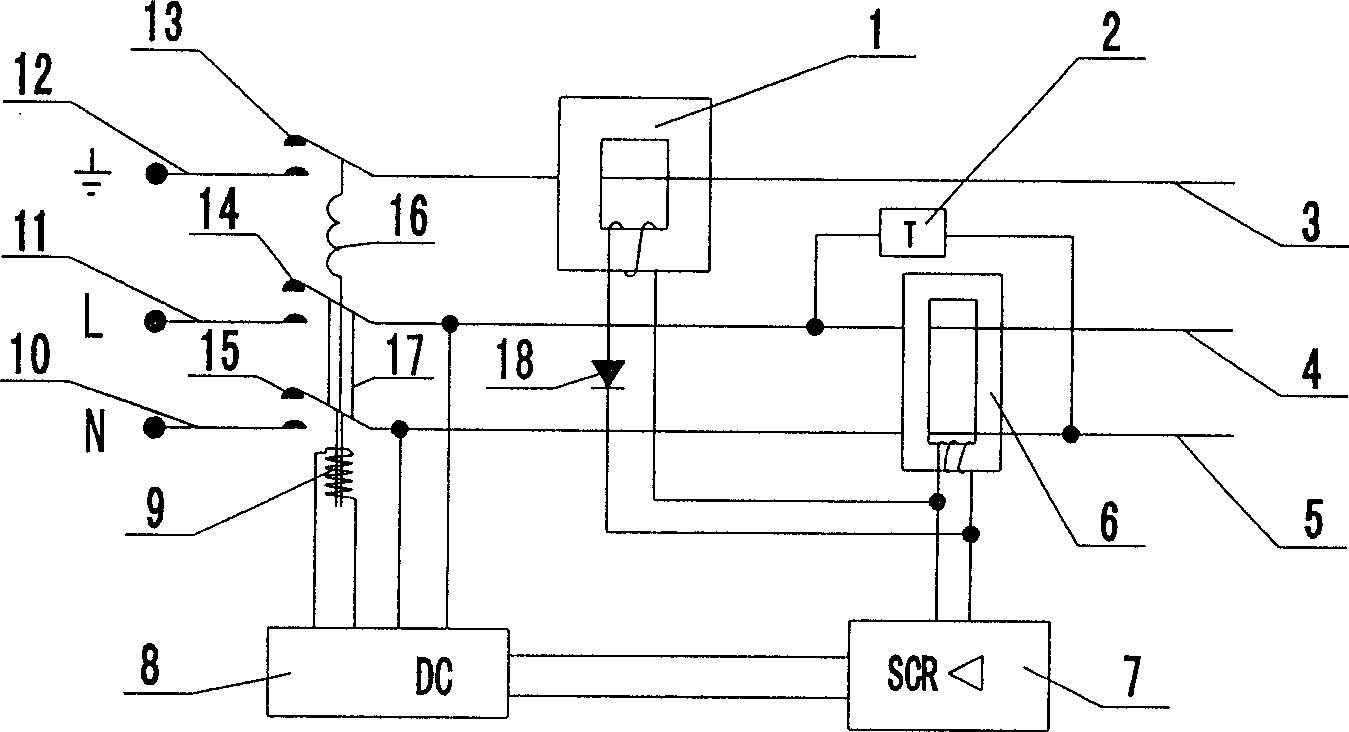
[0016] see figure 1 As shown, an embodiment of the present invention, the all-round leakage protection plug is composed of a zero-sequence current transformer 6, a ground wire electrification detection sensor 1, an amplifier circuit 7, a test circuit 2, a free release device 9, a breaker 17, and a grounding sequence device , High temperature resistant, flame retardant internal connecting wires 10, 11, 12, DC power supply 8, and power cords 3, 4, 5. The grounding sequence device is composed of a pair of ground wire contacts 13, a breaker 17, and a spring 16. The two ends of the spring 16 are respectively connected with the upper end of the push-pull rod of the breaker 17 and the copper reed of the ground wire moving contact 13, so that the ground wire The moving and static contacts of the moving contact 13 always have a spring force that attracts each other. In this way, when the free release 9 drives the breaker 17 to move up or down, the phase line contact 14 and the neutral ...

Embodiment 2

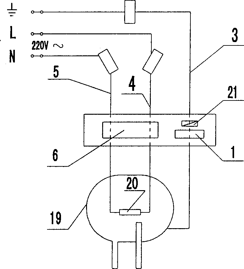
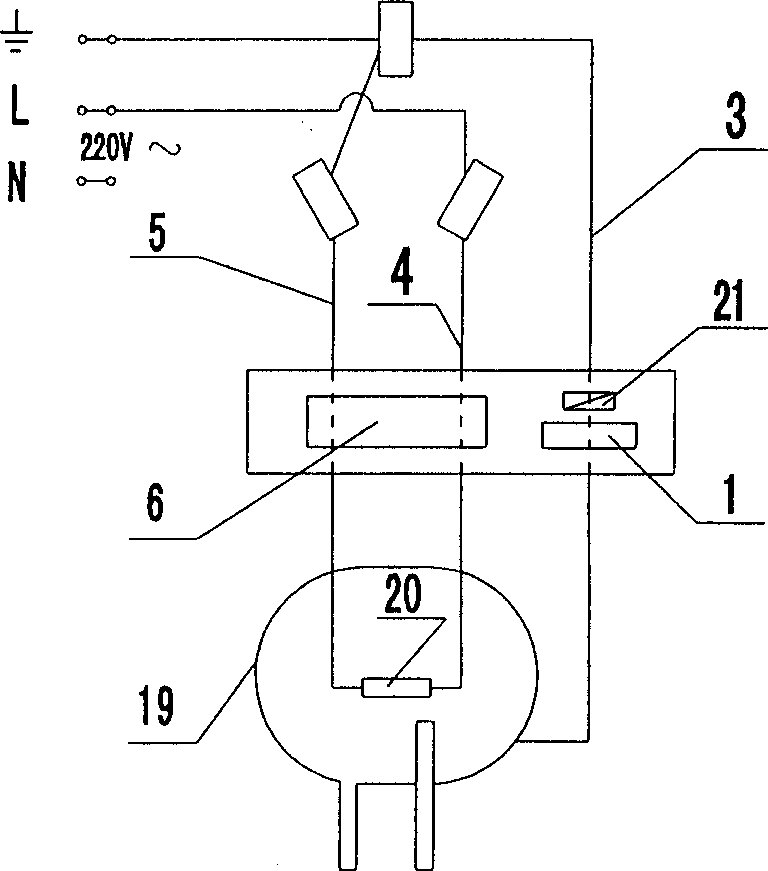
[0018] see figure 2 , image 3 Shown, the present invention is applied to an embodiment on the electric water heater. The phase and neutral wires 4 and 5 of the power line are connected to the load 20 of the water heater 19, and the ground wire 3 is connected to the shell. The phase and zero wires 4 and 5 of the power line pass through the zero-sequence current line sensor 6 and are connected to the phase and zero pole copper pins of the plug, and the ground wire passes through the inductor 1 and is connected to the ground pole copper pin through the grounding sequence device. When the water heater load 20 leaks electricity, there is a residual current between the phase and neutral wires 4 and 5, or when the local wire 3 has a current due to unexpected reasons, the zero-sequence current transformer 6 or the secondary of the inductor 1 will generate a signal. When the residual current or leakage current is greater than a specified value (such as 10mA or 50mA), the three pole...


PUM


Abstract

A multi-function leakge protection plug not only can prevent the electric shock accident caused by electrical appliance fault but also can prevent the electric shock accident caused by the power source fault. Therefore, it has earth line live line detecting inductor in the earth line of power source line, zero sequence current mutual inductor, a pair of contact terminal setting between the sub-breaker to each line of phase, zero and earth within the plug, a spring at between the sub-breaker upper end and the copper leaf of earth line active contact terminal to let the spring force attracting to each other always exist on the pair of earth line contact terminal. The safety requirement in electrical operation can be achieved by connecting earth line first and then phase and zero lines or cutting of phase and zero lines first and then earth line when the free releasing device is acting No matter the residual current exists between phase and zero lines or the abnormal cunent exists on theearth line three electrodes in the plug will be cut off simultaneously.

Description

technical field [0001] The invention relates to the technical field of electricity safety protection, in particular to an all-round electric leakage protection plug. Background technique [0002] The existing leakage protector can only detect whether there is residual current between the phase and neutral lines of the load line. When the residual current occurs and reaches a certain value (for example, 10mA), it will act and cut off the phase and neutral lines. Therefore, it can only implement protection for subsequent load fault leakage. However, a large number of facts prove that even if there is no fault in the load, due to a power failure, such as a wrong connection of the power supply, it is not the phase line in and the neutral line out, but the phase line in and the ground line out, or the insulation between the power phase and ground is damaged. , and in the case of poor grounding, the load (electrical appliance) shell will be charged, resulting in electric shock ac...

Claims


Application Information

Patent Timeline
IPC IPC(8): H01R13/66H01R13/70H02H3/32
Inventor 刘锦泰
Owner 刘睿刚
Learn More