Method for compensating mechanical vibration in machine

A mechanical vibration and machine technology, applied in mechanical vibration control, general parts of printing machinery, mechanical equipment, etc., can solve problems such as hidden measurement errors

Inactive Publication Date: 2002-05-29
HEIDELBERGER DRUCKMASCHINEN AG
View PDF6 Cites 5 Cited by
  • Summary
  • Abstract
  • Description
  • Claims
  • Application Information

AI Technical Summary

Problems solved by technology

Furthermore, the common sampling used to determine vibrations carries the risk of measurement errors caused by other disturbances

Method used


Image

  • Method for compensating mechanical vibration in machine
  • Method for compensating mechanical vibration in machine

Examples


Embodiment Construction

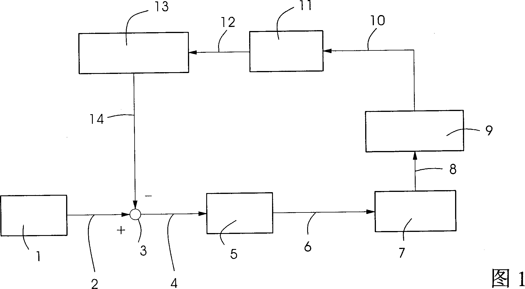
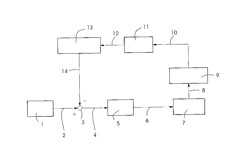
[0031] The printing machine of the present invention and the working steps of the method of the present invention will be described in detail with reference to FIG. 1 and subsequent embodiments. Without loss of generality, it is shown that for a certain circular frequency ω s or compensation for mechanical vibration or disturbance of a machine shaft of machine frequency order r, where r is a real number. Because for a certain circular frequency ω s The compensation of the mechanical vibration or disturbance is carried out in a manner independent of other circular frequencies or orders, the so-called superposition principle, so this method can especially be used for any number of different circular frequencies ω si or order r i Compensation is performed, where i is a natural number, and the method can be used both simultaneously and sequentially. This makes it possible for the machine shaft to turn at a constant speed even when non-uniform moments act on it.

[0032] In the...


PUM


Abstract

The invention proposes a method for compensating for a mechanical oscillation which has a frequency spectrum which can be approximately represented by a number of discrete frequency components, at a machine shaft via at least one actuator acting directly or indirectly upon the machine shaft. At least upon one of the discrete frequency components of the mechanical oscillation is superposed by the actuator, independently of the other frequency components, at least one substantially harmonic torque of the same frequency having a specific amplitude and phase in such a manner that the amplitude of the oscillation of the machine shaft at the this frequency is reduced.

Description

technical field [0001] The invention relates to a method for compensating mechanical vibrations, in particular rotational vibrations, on a machine shaft, especially on a printing unit or printing press shaft, by means of at least one actuator acting directly or indirectly on the machine shaft, said vibrations having A spectrum that can be approximated by a number of discrete frequency components. [0002] Furthermore, the invention relates to a printing unit having at least one machine shaft driven by means of an actuator and a measuring device for recording mechanical vibrations of the machine shaft. Background technique [0003] Mechanical vibration not only refers to the periodic change of one or more coordinates of the machine shaft, such as rotational vibration, vibration swing, etc., but also refers to the superposition or overlap of multiple periodic changes. In the following, the term "machine axis" is used to designate an axis of rotation in the mathematical sense,...

Claims


Application Information

Patent Timeline
Patent Type & Authority Applications(China)
IPC IPC(8): B41F33/00B23Q11/00F16F15/02G05D19/02
CPCF16F15/02G05D19/02B23Q11/0032B41F13/0008
Inventor 马蒂亚斯·内尔
Owner HEIDELBERGER DRUCKMASCHINEN AG
Why Eureka
Try Eureka