Fin tube heat exchanger

A finned tube and fin technology, applied in the field of heat exchangers, can solve problems such as short die life, insufficient heat exchange performance, and blocked airflow

Inactive Publication Date: 2002-06-19
POSTECH ACAD IND FOUND +1
View PDF1 Cites 7 Cited by
  • Summary
  • Abstract
  • Description
  • Claims
  • Application Information

AI Technical Summary

Problems solved by technology

Therefore, the heat exchange performance between the air and the fins is insufficient
Additionally, raised portions formed across the width of the fins can block airflow, thereby increasing pressure drop
This can cause annoying noise
In addition, an excessive number of protrusions results in higher manufacturing costs and a shorter life of the die for finned parts

Method used


Image

  • Fin tube heat exchanger
  • Fin tube heat exchanger
  • Fin tube heat exchanger

Examples


Embodiment Construction

[0022] Detailed description of the preferred embodiment

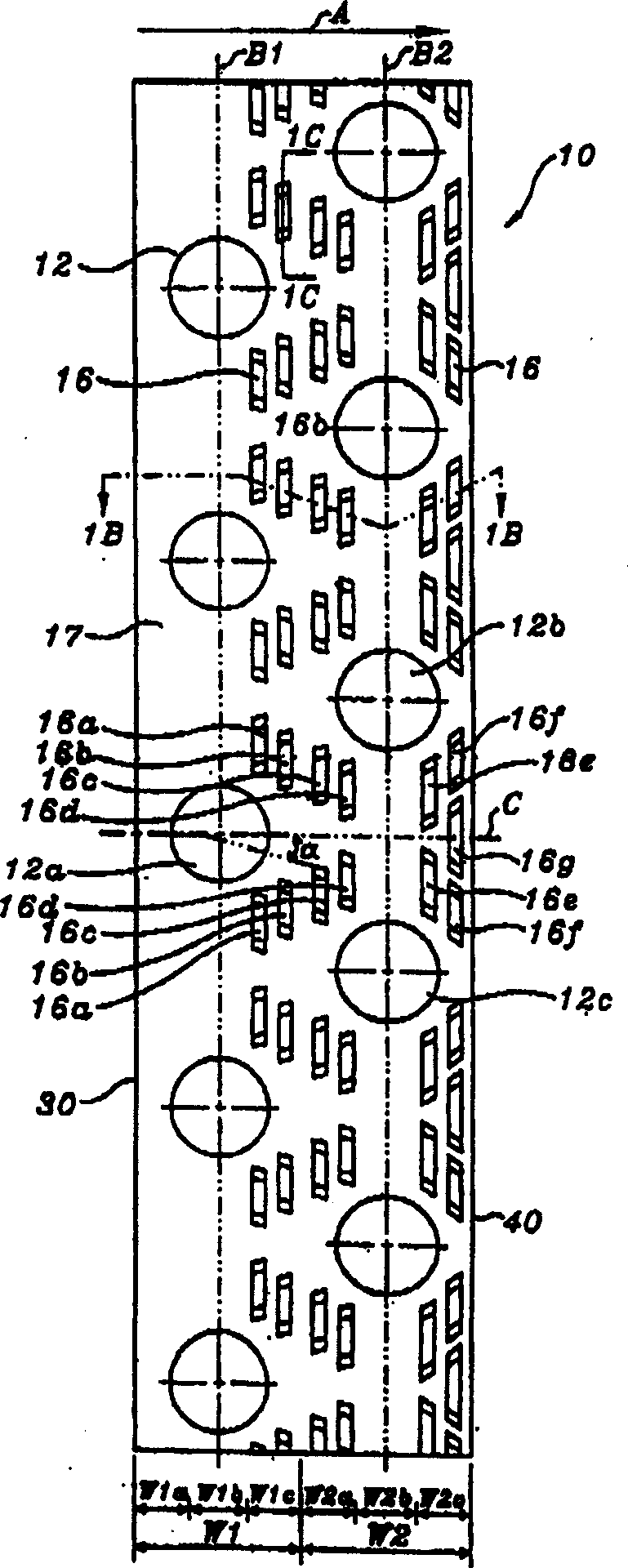
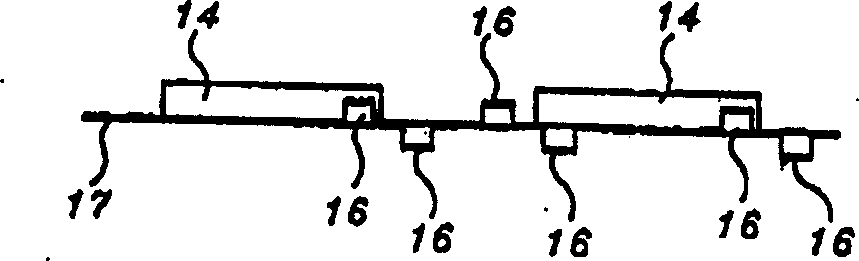
[0023] refer to Figure 1A-Figure 1C , The finned tube heat exchanger according to the first embodiment of the present invention has a plurality of thin plate-shaped aluminum fin members 10 . The fin members 10 are spaced at regular intervals and parallel to each other. Two rows B1 and B2 of a plurality of through holes 12 regularly spaced apart are formed in each plate-shaped fin member 10 along its length. A heat exchange tube is inserted into each through hole 12 . The through-holes 12 of the rear row B2 are offset in the airflow direction A from the through-holes 12 of the front row B1 and are located therebetween. Preferably, each through-hole 12 of the rear row B2 is arranged on a direction line passing through the middle between adjacent through-holes of the front row B1. An annular fin ring 14 is integrally formed on the fin member around each through hole 12 so that heat exchange between the tubes and the f...


PUM


Abstract

A fin tube heat exchanger includes a plurality of plate-shaped elongated fin members(110)spaced at regular intervals in parallel with one another. Each fin member has a fin base, a plurality of through-holes(112)in two rows in a longitudinal direction of the fin member and a plurality of raised portions with legs. A plurality of heat exchanger tubes are inserted into the through-holes. Each fin member has flat areas at a front and middle regions of a front half and a middle region of a rear half. The raised portion disposed at a rear region of the front half and a front region of the rear half has the legs inclined by a predetermined angle with respect to a traverse centerline which passes through the center of an adjacent through-hole of the front row. The distance from the centerline is generally increased. Each fin member has a front edge and a rear edge. The front edge has protruded portions and recessed portions and the rear edge has protruded portions and recessed portions. The protruded portion of the front edge substantially corresponds to the recessed portion of the rear edge disposed on the same traverse centerline.

Description

technical field [0001] The invention relates to a heat exchanger having a plurality of fins for exchanging heat between two fluids, for example a refrigerant medium and air or the like. Background technique [0002] Many attempts have been made to improve the performance of finned tube heat exchangers used in air conditioners or refrigerators. In particular, improvements in the structure of thin plate-shaped fin members of finned tube heat exchangers have been accomplished in order to obtain higher heat exchanging performance. [0003] In order to improve the performance of the heat exchanger, a plurality of concave and convex portions are formed on each fin member. For example, US Patent No. 4,832,117 to KATO discloses a thin plate-shaped fin member having a plurality of raised portions. Each fin member has a fin-shaped base on which are formed aligned through-holes and a plurality of raised portions. The legs of the raised portion are angled relative to the longitudinal...

Claims


Application Information

Patent Timeline
Patent Type & Authority Applications(China)
IPC IPC(8): F28D1/00F28F1/32
CPCF28F1/325F28D1/00
Inventor 姜熙瓒金武焕
Owner POSTECH ACAD IND FOUND
Why Eureka
Try Eureka