
Fixture for laser welding

A laser welding jig and clamping device technology, which is applied to laser welding equipment, welding equipment, manufacturing tools, etc., can solve the problems of inconvenient operation and lower work efficiency, and achieve the effect of convenient clamping and high work efficiency

Inactive Publication Date: 2002-07-03
HUAZHONG UNIV OF SCI & TECH
View PDF0 Cites 16 Cited by
  • Summary
  • Abstract
  • Description
  • Claims
  • Application Information

AI Technical Summary

Problems solved by technology

If there is a cutter head that is not adjusted properly, all the clamps must be loosened and re-clamped, which is inconvenient to operate and reduces work efficiency.

Method used


Image

  • Fixture for laser welding
  • Fixture for laser welding
  • Fixture for laser welding

Examples


Embodiment Construction

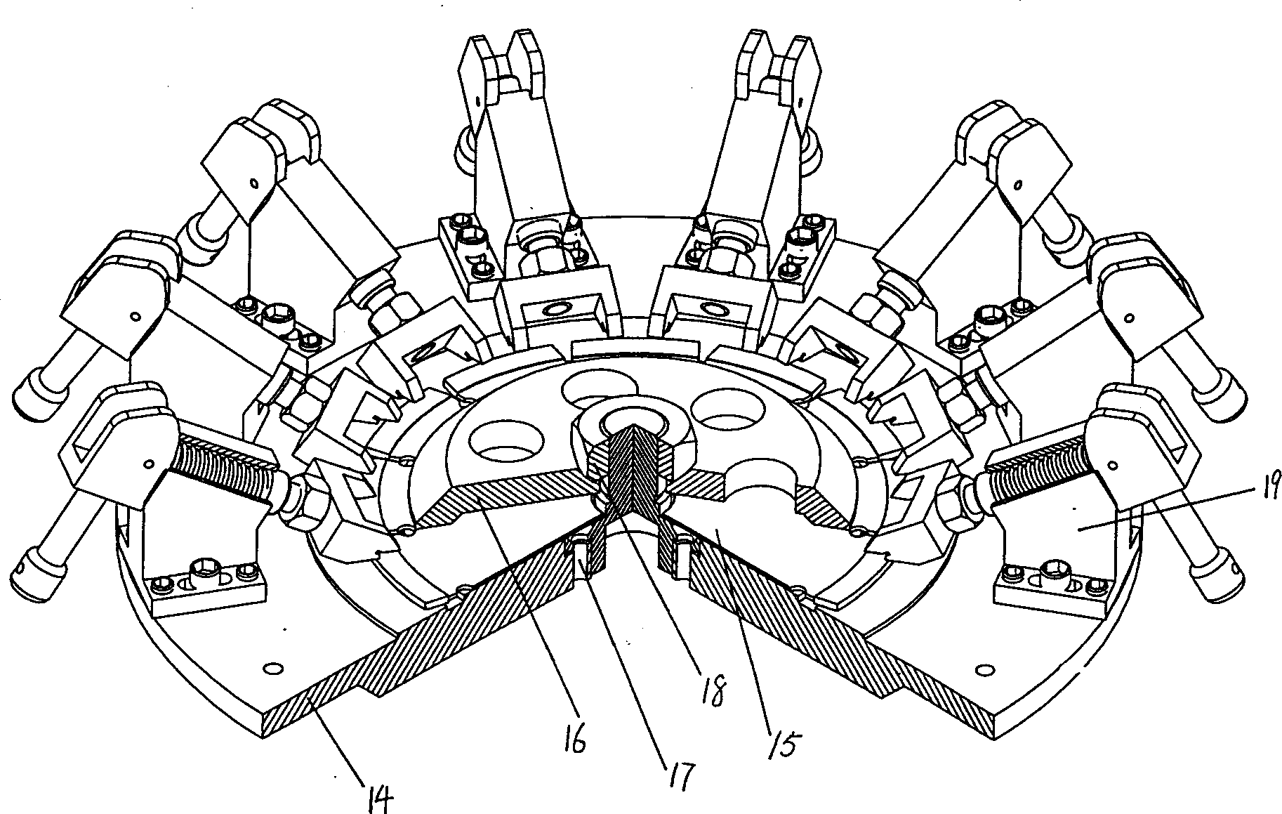
[0010] Such as figure 1 As shown, the chassis 14, the saw blade base 15, and the cover plate 16 are provided with a number of positioning holes 17, and in the center of them are provided with threaded central holes for fastening nuts 18, and several clamping devices 19 are installed on the chassis. 14 on.

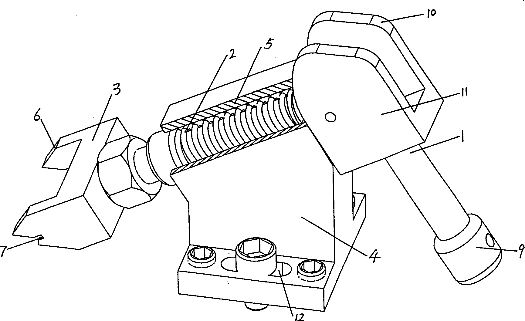
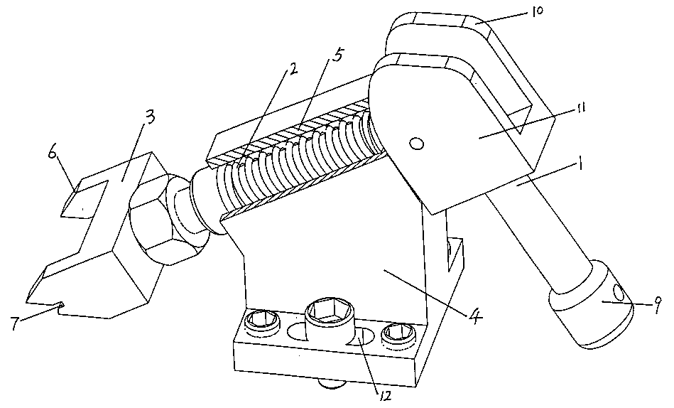
[0011] The structural representation of clamping device 19 is as figure 2 shown. The clamping device consists of an eccentric pull rod 1, a spring 2, a pressure head 3 and a base 4.

[0012] Indenter 3 is shape, The protruding portion 6 of the protruding portion is wedge-shaped, and the space left between the two protruding portions should be convenient for picking and placing the cutter head. The included angle θ between the wedge-shaped bottom edge of the protruding portion 6 and the upper surface of the indenter 3 should be Between 10-60°, and a groove 7 is opened at the bottom of the protruding part. The protruding part 6 and the groove 7 can clamp the cutter h...


PUM


Abstract

A fixture for laser welding is composed of base plate, cover plate, fastening nut, locating hole and lamping unit. The said clamping unit installed on base plate consists of eccentric pull rod, spring, pressing head and base. Its pressing head is such improved that it has a central recess and two wedge-shaped side parts. Its advantages include convenient operation and high working efficiency.

Description

technical field [0001] The invention relates to a jig, in particular to a laser welding jig, especially a welding jig for laser welding a diamond circular saw blade. Background technique [0002] In the process of laser processing, it is often necessary to use various types of fixtures. The same is true in the welding process of diamond circular saw blades. Due to the advantages of convenient use, wide application range and high processing efficiency, diamond circular saw blades are more and more widely used in construction, stone processing and road construction, which also drives the production of diamond circular saw blades. In the production process of diamond circular saw blades, one of the important processes is to weld the diamond cutter head to the substrate, and laser welding is usually used at present. In the laser welding process, it is necessary to use fixtures, that is, welding fixtures. Existing laser welding fixtures have a common problem, that is, they mus...

Claims


Application Information

Patent Timeline
IPC IPC(8): B23K26/08
Inventor 唐霞辉朱国富何艳艳周毅
Owner HUAZHONG UNIV OF SCI & TECH
Features
  • Generate Ideas
  • Intellectual Property
  • Life Sciences
  • Materials
  • Tech Scout
  • Unparalleled Data Quality
  • Higher Quality Content
  • 60% Fewer Hallucinations
Learn More