
Pilot differential valve with metering function

A pilot-operated, valve technology, applied in the direction of lift valve, valve details, valve device, etc., can solve the problems of large volume and weight, unacceptable and so on

Inactive Publication Date: 2002-07-03
HARBIN ENG UNIV
View PDF0 Cites 7 Cited by
  • Summary
  • Abstract
  • Description
  • Claims
  • Application Information

AI Technical Summary

Problems solved by technology

Obviously, when the pipe diameter is large, the volume and weight of the combination of the above three parts are very large, which is not easy for people to accept.

Method used


Image

  • Pilot differential valve with metering function
  • Pilot differential valve with metering function
  • Pilot differential valve with metering function

Examples


Embodiment Construction

[0006] Provide the preferred scheme of implementing the present invention below, and illustrate in conjunction with accompanying drawing.

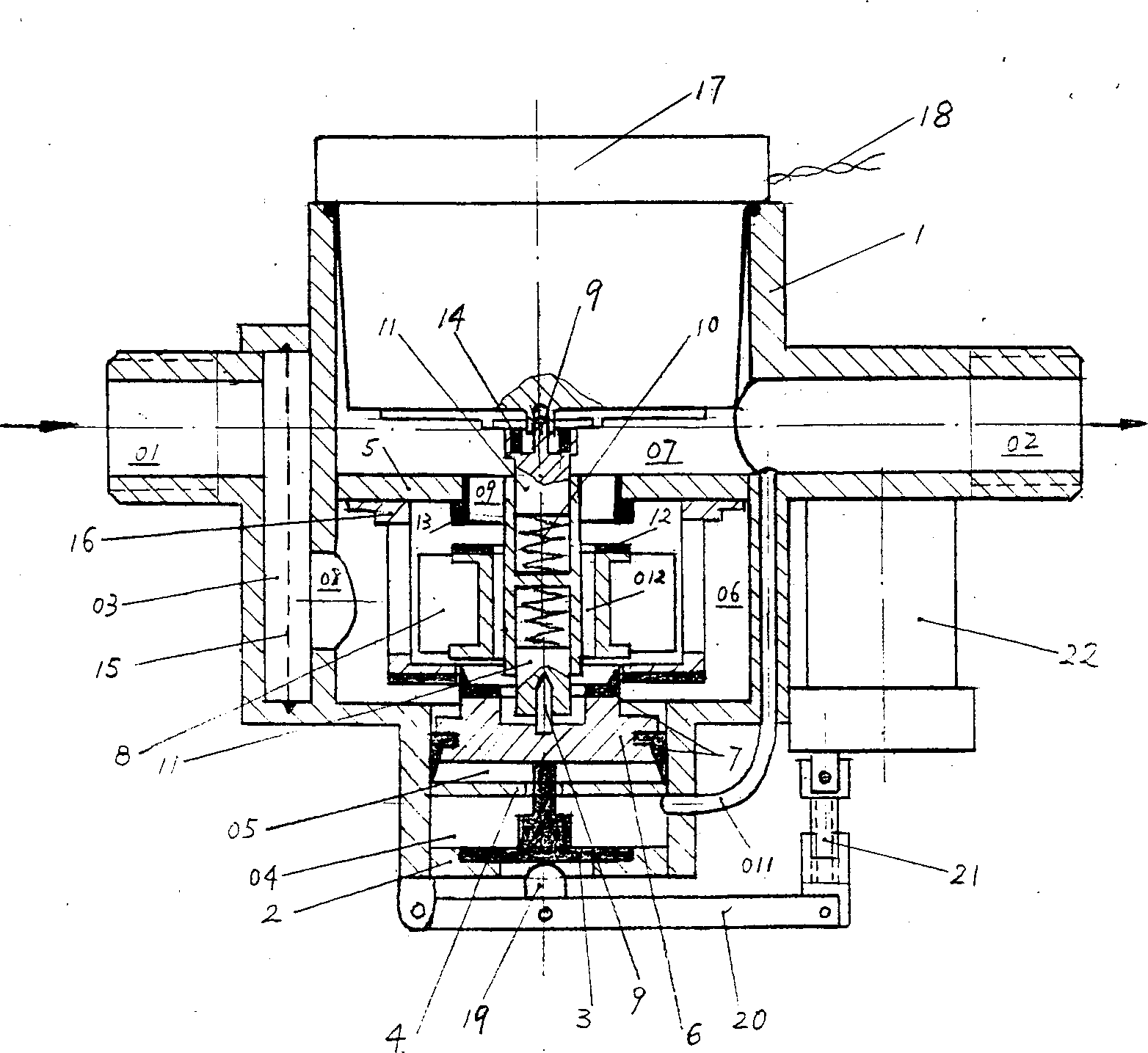
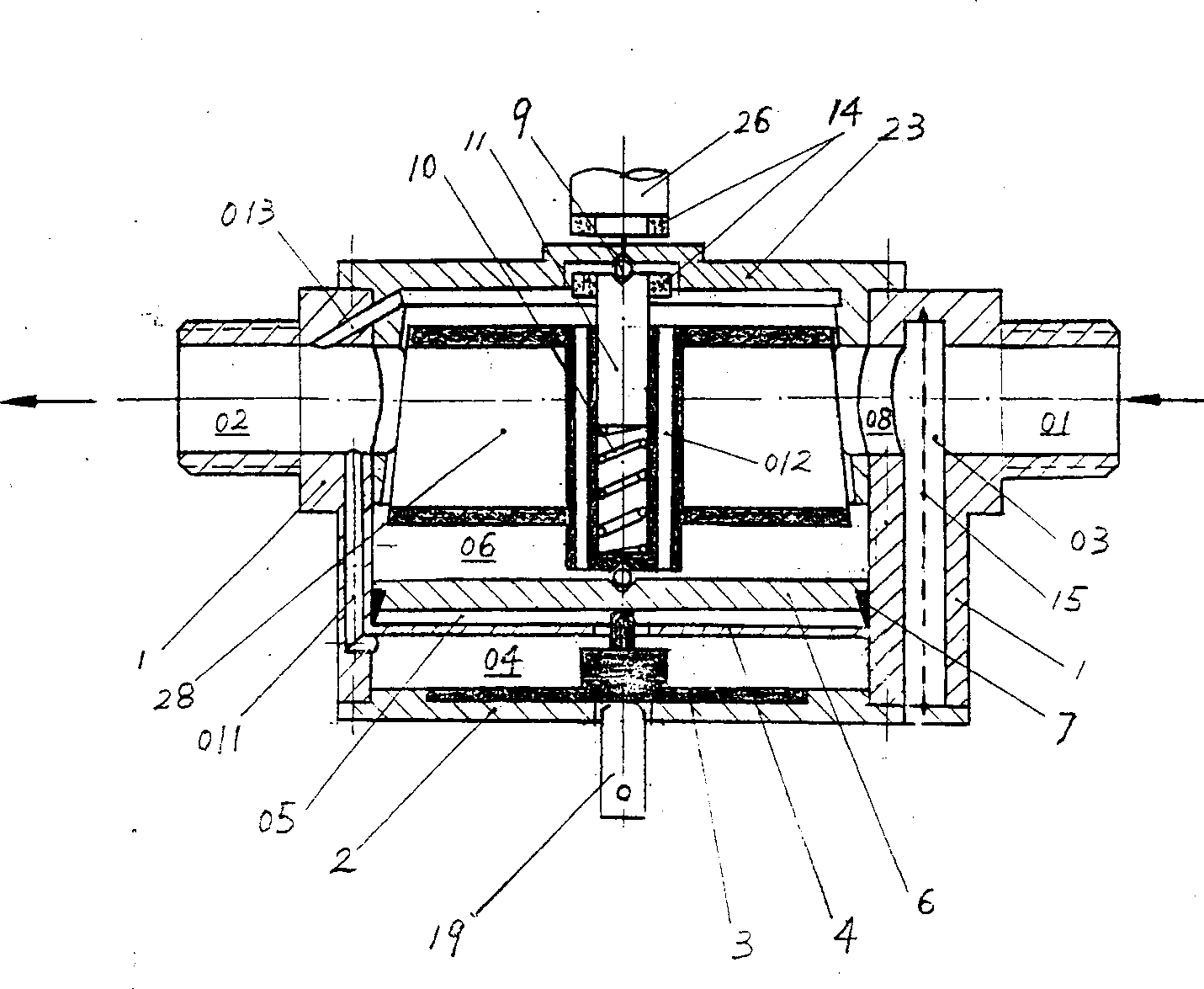
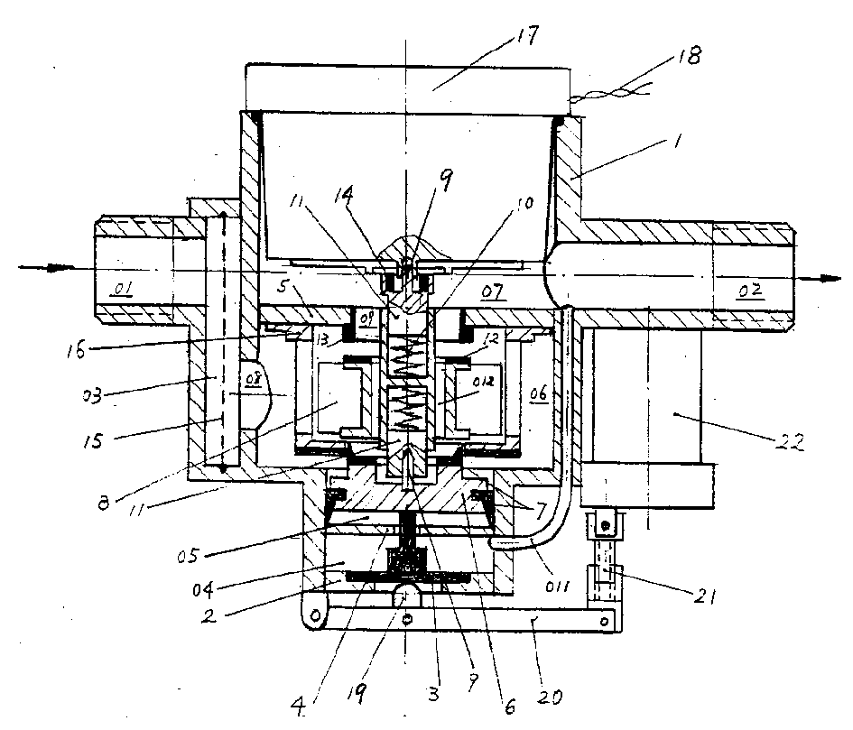
[0007] like figure 1 The first design scheme of the pilot-operated differential valve with metering function shown is composed of a housing (1), an end cover (2), a diaphragm (3), a lower partition (4), an upper partition (5) , piston (6), rubber ring (7), impeller (8), bearing (9), spring (10), short shaft (11), valve plug (12), valve seat (13), permanent magnet ring (14 ), filter screen (15), shroud (16), water meter head (17), measurement pulse lead wire (18), pressure head (19), lever (20), screw pair (21) and motor (22) constitute. Wherein the housing (1) is divided into two chambers. Fluid first enters the filter chamber (03) through the inlet (01), and there is a filter screen (15) inside to prevent slightly larger particles from entering the working chamber behind and hindering the action of the movable components. The filter c...


PUM


Abstract

A pilot-type differential valve with metering function for the water meter system with IC card pre-charge function features that the meter, blade wheel, permanent-magnetic ring and guide cover of traditional water meter and the partition, piston, valve plug and valve seat of pilot-type differential valve are assembled in a single casing, and a specia blade wheel structure is used, which features that the blade wheel is separated from its axle for moving up and down under the action of spring. Its advantages include light weight low cost small size.

Description

technical field [0001] A pilot-operated differential valve with metering function is a combination of water meter head, impeller, permanent magnet ring, shroud and pilot-operated differential valve main parts installed in the same housing, used for fluid delivery pipes In the road, it can be used online with the controller to achieve the purpose of metering, billing and automatic on-off water supply. Background technique [0002] At present, IC card prepaid water, electricity and gas systems will gradually be used in residents, factories, mines, enterprises and institutions. As far as the prepaid water meter system is concerned, its design idea is that the charging unit "writes" the water consumption purchased by the user into the IC card. Identify and open the electronic control valve, and the user can use water. The water consumption is accumulated by the water meter and fed back to the single-chip microcomputer. In addition to displaying it on the LCD screen, it is also...

Claims


Application Information

Patent Timeline
IPC IPC(8): F16K1/00F16K31/04F16K31/122F16K37/00G01F1/075
Inventor 郑全逸
Owner HARBIN ENG UNIV
Learn More