Carding machine

A technology of carding machine and dirt, applied in the field of carding machine, can solve the problem of difficult to achieve siphon and so on

Inactive Publication Date: 2002-07-17
MASCHINENFABRIK RIETER AG
View PDF2 Cites 10 Cited by
  • Summary
  • Abstract
  • Description
  • Claims
  • Application Information

AI Technical Summary

Problems solved by technology

But due to the necessary size of the tank, it is difficult to achieve the ...

Method used


Image

  • Carding machine
  • Carding machine

Examples


Embodiment Construction

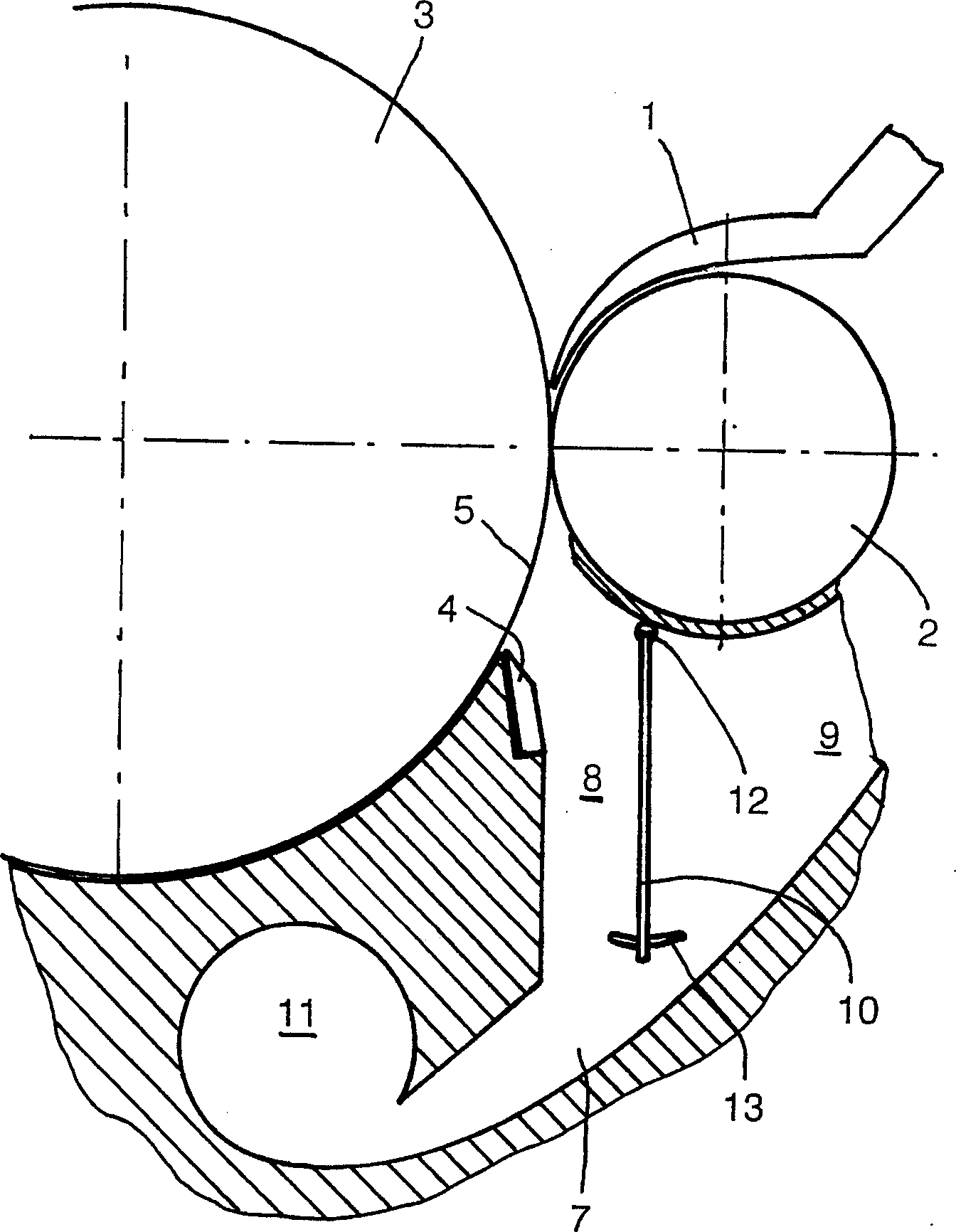
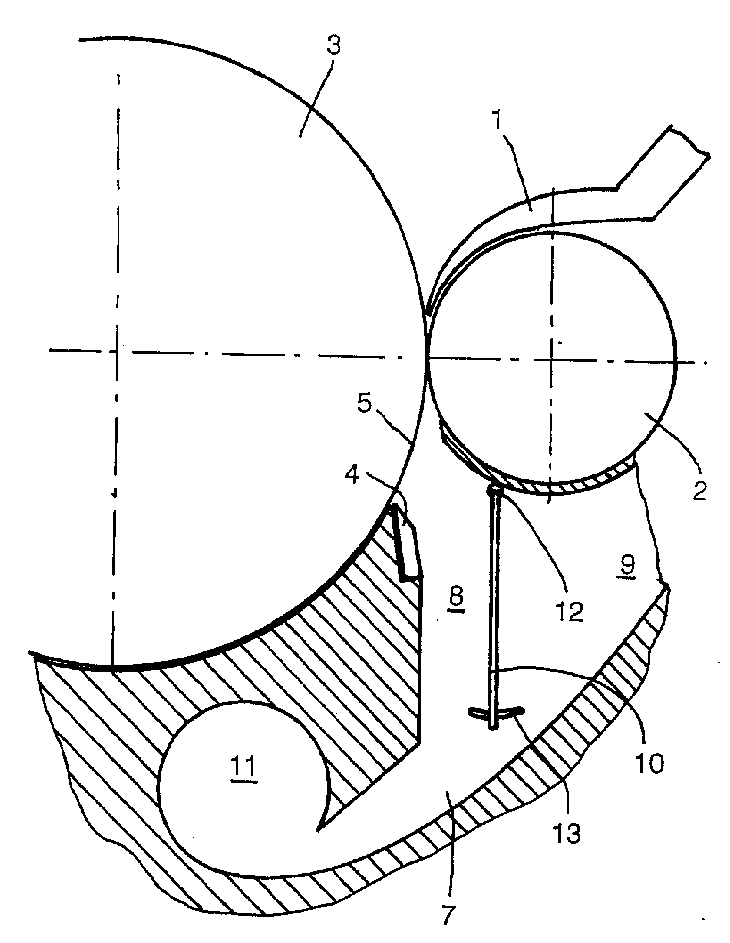
[0022] In the suction zone where the fibers are fed into the card, not shown, a feed disc 1 cooperating with a feed roll 2 is provided. Between the feeding tray 1 and the feeding roller 2, the fiber plush bundle is sent to the opening roller 3 in the form of fleece, and the opening roller is also called licker-in roller or licker-in roller. The opening roller 3 separates the fibers introduced into the individual fiber strands. The impurities contained in the pile fabric are fed to the feed roller 2 and the opening roller 3 together with the fibers. Due to the centrifugal force acting on the impurities, these impurities are centrifugally removed from the opening roller 3 on the opening roller 3, or at least, the lighter or more inert good fibers are carried further by the opening roller 3 due to their mass. rise. It is also beneficial to separate the dirt particles from the good fibers by means of a separating knife 4 which defines a dirt separating hole 5 in the shell 6 of t...


PUM


Abstract

A textile carding machine has a feed roller advancing a non-woven fibres to a separation roller. The foreign body separation hole is disposed in the discharge roller zone to separate the fiber and the foreign body. The outlet has a discharge passage with a discharge zone and an air flow zone. The foreign body outlet zone is disposed in the zone of foreign body separation hole and separated from the air flow zone. A curtain is arranged in the foreign body separation zone and air flow zone for the purpose of preventing against interference of the discharge of the foreign body inside the air flow.

Description

technical field [0001] The invention relates to a carding machine with a feed roller, by means of which fibers can be conveyed in the form of fiber laps to the opening roller, whereby dirt separation holes are provided in the area of ​​the opening roller in order to remove dirt The fiber is separated from the impurities at the separation hole, and a channel is set at the dirt separation hole to guide the impurities to leave, and the channel forms a dirt removal area and an air intake area. Background technique [0002] US-P3955244 discloses a carding machine with a feed roller and an opening roller formed with a plurality of dirt separation holes. The dirt separation zone is basically divided into two parts. In the first section following the feed roller there are provided large holes for the separation of coarser dirt, followed by an area in which a plurality of rods are arranged at a distance from each other. The gaps between the rods are especially useful for separating...

Claims


Application Information

Patent Timeline
IPC IPC(8): D01G15/82
CPCD01G15/825
Inventor W·斯格P·莫罗夫
Owner MASCHINENFABRIK RIETER AG
Why Eureka
Try Eureka