
Paper cutter with cutting knife moving vertically

A technology of vertical movement and paper cutting machine, which is applied to printing machines, rotary printing machines, printing, etc., and can solve the problems that it is impossible to make the best use of everything and it is difficult to meet the specification requirements.

Inactive Publication Date: 2002-07-24
贾永康
View PDF0 Cites 7 Cited by
  • Summary
  • Abstract
  • Description
  • Claims
  • Application Information

AI Technical Summary

Problems solved by technology

The most important thing is that the paper must be pressed, so the size after the knife must be limited, so the accuracy of the final knife of the finished product still depends entirely on the technical level of the operator, and it is difficult to meet the final unified specification requirements
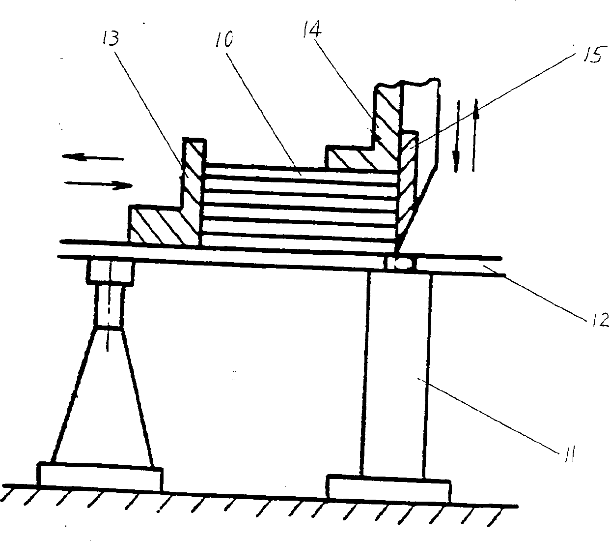
In addition, the steel edge of the blade of this paper cutter 15 is generally about 70mm, and it is impossible to make the best use of it by using the adjustment of the connecting rod.

Method used


Image

  • Paper cutter with cutting knife moving vertically
  • Paper cutter with cutting knife moving vertically
  • Paper cutter with cutting knife moving vertically

Examples


Embodiment Construction

[0015] A kind of paper cutter embodiment that the blade moves vertically that the present invention designs is described in detail as follows in conjunction with accompanying drawing;

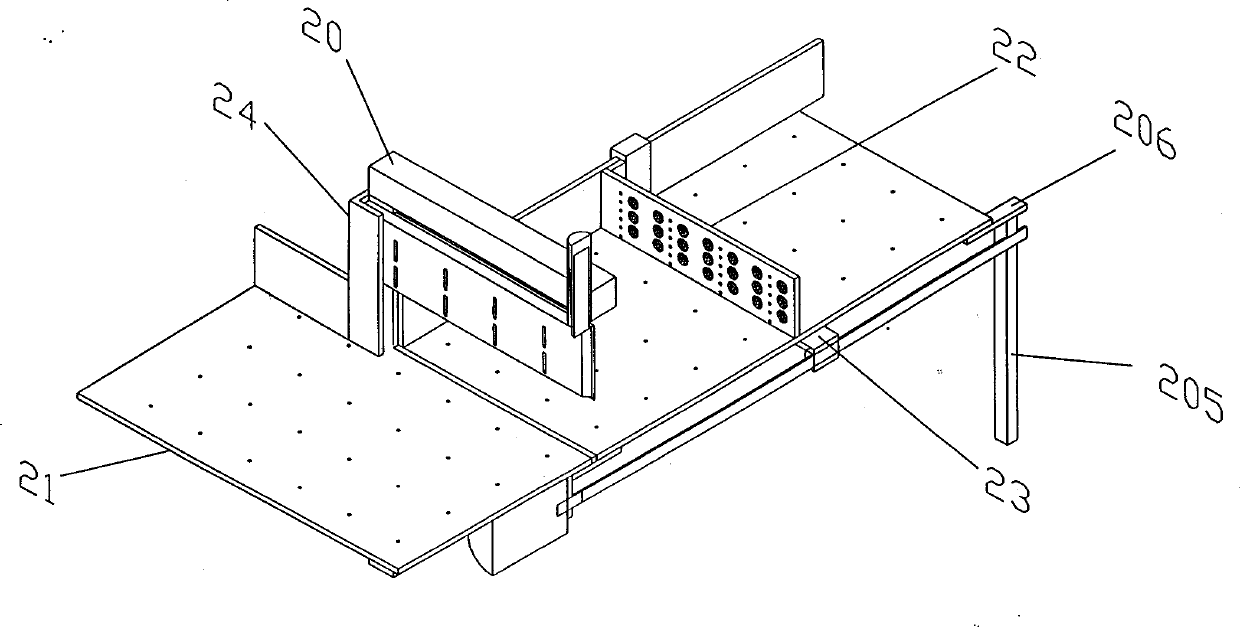
[0016] The overall structure of this embodiment is as figure 2 As shown in the figure, the structure of the left half sectioned along the longitudinal symmetrical axis of the paper cutter is shown in the figure, and the structure of the right half is completely symmetrical. This embodiment includes a frame 20, an air cushion workbench 21, a paper pusher 22 installed on the workbench, a motor and a screw drive mechanism 23, a knife bed system 24 and blades installed thereon. The above components are described in detail as follows:

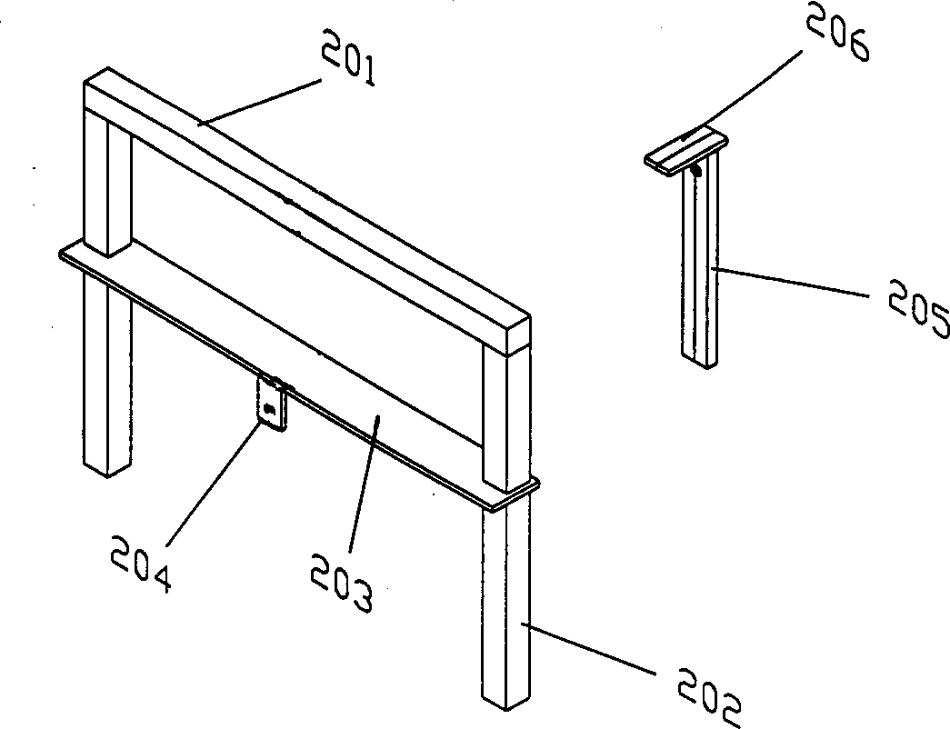
[0017] The rack structure of this embodiment is as image 3 As shown, it includes a frame composed of a top beam 201 and two columns 202 connected to its two ends, a front frame plate 203 installed on the two columns 202 and a motor support 204 installed on the bo...


PUM


Abstract

A paper cutter with cutting knife moving vertically is composed of support frame consisting of vertical piles and top beams, air-cushion bench, paper pusher with more vacuum sucking disks, motor-leading screw drive mechanism, knife holder, and knife. Said knife is linked to a electric hydraulic cylinder mounted to top beam for moving up and down. Its advantages are high cutting precision and high safety.

Description

technical field [0001] The invention belongs to the technical field of printing equipment, and in particular relates to the structural improvement of a paper cutter. Background technique [0002] The main structure of the traditional paper cutter is as follows: figure 1 Shown (published by Chemical Industry Press entitled "post-press processing", Jin Yinhe, September, 2001), including frame 11, the workbench 12 installed on the frame, the push paper arranged on the workbench Device 13, paper presser 14, driving device and the knife bed driven by it, and the paper cutter 15 installed on the knife bed; wherein the driving device is driven by a worm and gear controlled by a hydraulic clutch, and drives the knife bed for tilting motion through a connecting rod, so that The blade cuts at an angle. The paper pusher can not only push the paper forward, but also be used as a guide for positioning; the paper presser compresses the positioned paper 10, so as to avoid errors caused b...

Claims


Application Information

Patent Timeline
Patent Type & Authority Applications(China)
IPC IPC(8): B26D1/00B26D7/00B41F13/56B41F13/60
Inventor 贾永康
Owner 贾永康
Learn More