MR imaging method, phase error measuring method and MRI system

A phase error and imaging method technology, applied in the field of MR imaging, can solve problems such as image quality degradation, residual magnetism phase error, etc.

Inactive Publication Date: 2002-08-07
GE MEDICAL SYST GLOBAL TECH CO LLC
View PDF1 Cites 13 Cited by
  • Summary
  • Abstract
  • Description
  • Claims
  • Application Information

AI Technical Summary

Problems solved by technology

[0006] However, since the remanence at the beginning of the phase error measurement and the remanence at the beginning of the pulse sequence of the fast echo process are not always equal, there is a problem with the above conclusion, the premise of the prior art cannot be established, and the remanence produces a phase error and leads to image quality degradation

Method used


Image

  • MR imaging method, phase error measuring method and MRI system
  • MR imaging method, phase error measuring method and MRI system
  • MR imaging method, phase error measuring method and MRI system

Examples


no. 1 approach -

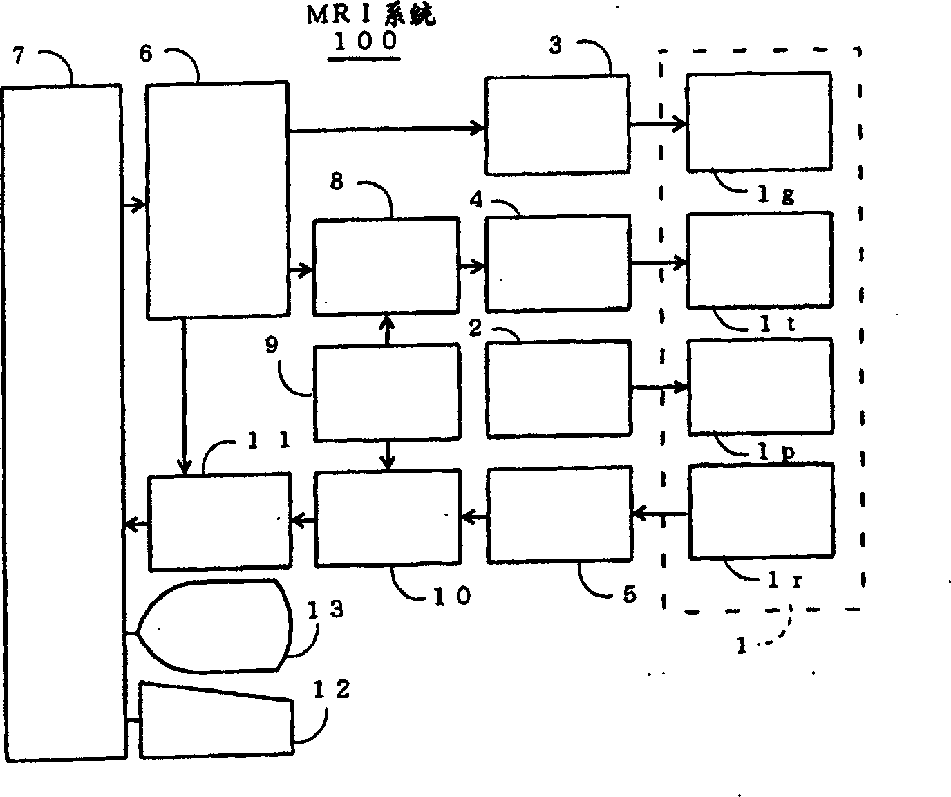
[0068] figure 1 is a block diagram of the MRI system according to the first embodiment of the present invention.

[0069] In the MRI system 100 of the present invention, there is a space (hole) in which the sample is placed on the magnet assembly 1, and a static magnetic field coil 1p that generates a constant static magnetic field in the sample is installed around it for layer selection axis, readout axis and phase A gradient or gradient magnetic field coil 1g for generating a gradient or gradient magnetic field, a transmitting coil 1t for providing RF pulses to excite nuclear spins in the sample, and a receiving coil 1r for detecting NMR signals from the sample. Static magnetic field coil 1p, gradient magnetic field coil 1g, transmitting coil 1t and receiving coil 1r are electrically connected to static magnetic field source 2, gradient or gradient magnetic field drive circuit 3, RF power amplifier 4 and preamplifier 5, respectively.

[0070] Sometimes, permanent magnets ca...

no. 2 approach -

[0112] Figure 10is a flowchart of an imaging scan according to the second embodiment.

[0113] In step W1 , the computer 7 generates an imaging sequence In and stores it in the sequence storage circuit 6 .

[0114] Such as Figure 11 As shown, the imaging sequence In leads to an imaging sequence in which, in the pulse sequence of a general fast spin echo process, a negative static or steady-state pre-pulse (ps, np) is applied before the excitation pulse R to correct Δ 0 The correction amount and used to correct Δ (n) The correction amount of is applied to the initial rewind pulse gyr. Then superimpose the correction amount on the subsequent rewinding pulse gyr to correct Δ (n) .

[0115] Refer again Figure 10 , in step W2, use Figure 11 The imaging sequence In shown acquires data to effectuate the scan.

[0116] According to the MRI system of the second embodiment described above, the remanence at the beginning of the pulse sequence of the fast spin echo process ...


PUM


Abstract

The present invention aims to reduce degradation in image quality due to residual magnetization. In a pulse sequence of a high-speed spin echo process, a pre-pulse is applied before an excitation pulse, and a correction pulse for correcting a phase error caused by the pre-pulse is applied before an initial inversion pulse.

Description

Background of the invention [0001] The present invention relates to an MR imaging method, a phase error measurement method, and an MRI (Magnetic Resonance Imaging) system, more precisely, an MR imaging method capable of reducing image quality degradation due to residual magnetism, a A phase error measuring method for measuring a phase error due to residual magnetism, and an MRI system implementing the above method. [0002] The following prior art has been disclosed in Japanese Patent Application Publication No. H10-75840. [0003] (1) A phase error measurement method implementing a pre-scan sequence, which is used to transmit an excitation pulse, transmit an inversion pulse, apply a phase encoding pulse on the phase axis, apply a readout pulse on the readout axis, and A rewind pulse is applied on the phase axis, followed by an inversion pulse, a dephasing pulse is applied on the phase axis, and data from the echo is acquired while a readout pulse is applied on the phase axis...

Claims


Application Information

Patent Timeline
Patent Type & Authority Applications(China)
IPC IPC(8): G01N24/08A61B5/055G01R33/46G01R33/48G01R33/565
CPCG01R33/56518G01R33/56563
Inventor 宫本昭荣
Owner GE MEDICAL SYST GLOBAL TECH CO LLC
Why Eureka
Try Eureka