
Mechanical propelling pencil

A technology for mechanical pencils and lead cores, applied in mechanical pencils, printing, writing utensils, etc., can solve the problems of insufficient use of lead cores and waste of resources

Inactive Publication Date: 2002-08-21
KOTOBUKI & CO LTD
View PDF0 Cites 8 Cited by
  • Summary
  • Abstract
  • Description
  • Claims
  • Application Information

AI Technical Summary

Problems solved by technology

As a result, lead cores that are shorter than the distance from the core feeding mechanism to the front end of the pen holder cannot be fully utilized, resulting in a waste of resources as waste lead cores

Method used


Image

  • Mechanical propelling pencil
  • Mechanical propelling pencil
  • Mechanical propelling pencil

Examples


Embodiment Construction

[0015] Embodiments of the present invention will be described below using the drawings. Figure 1 to Figure 3 represent the invention

[0016] Diagram of the implementation form.

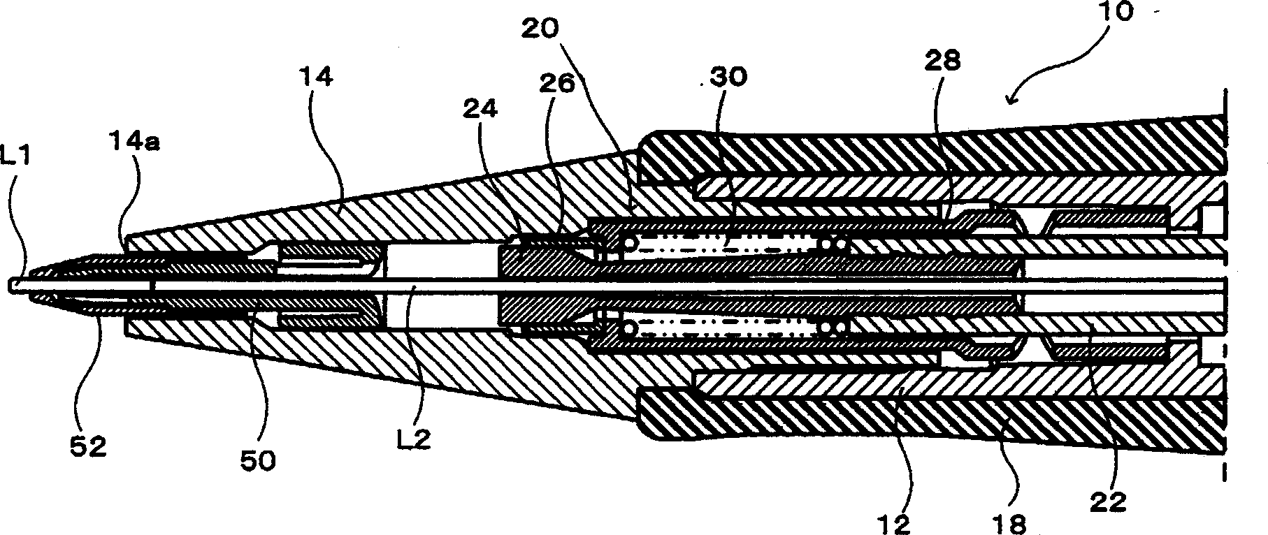
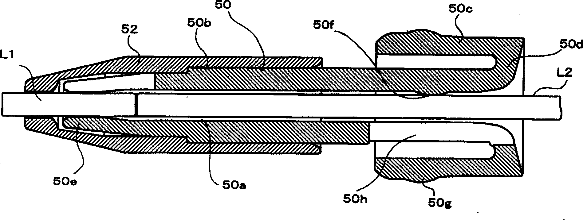
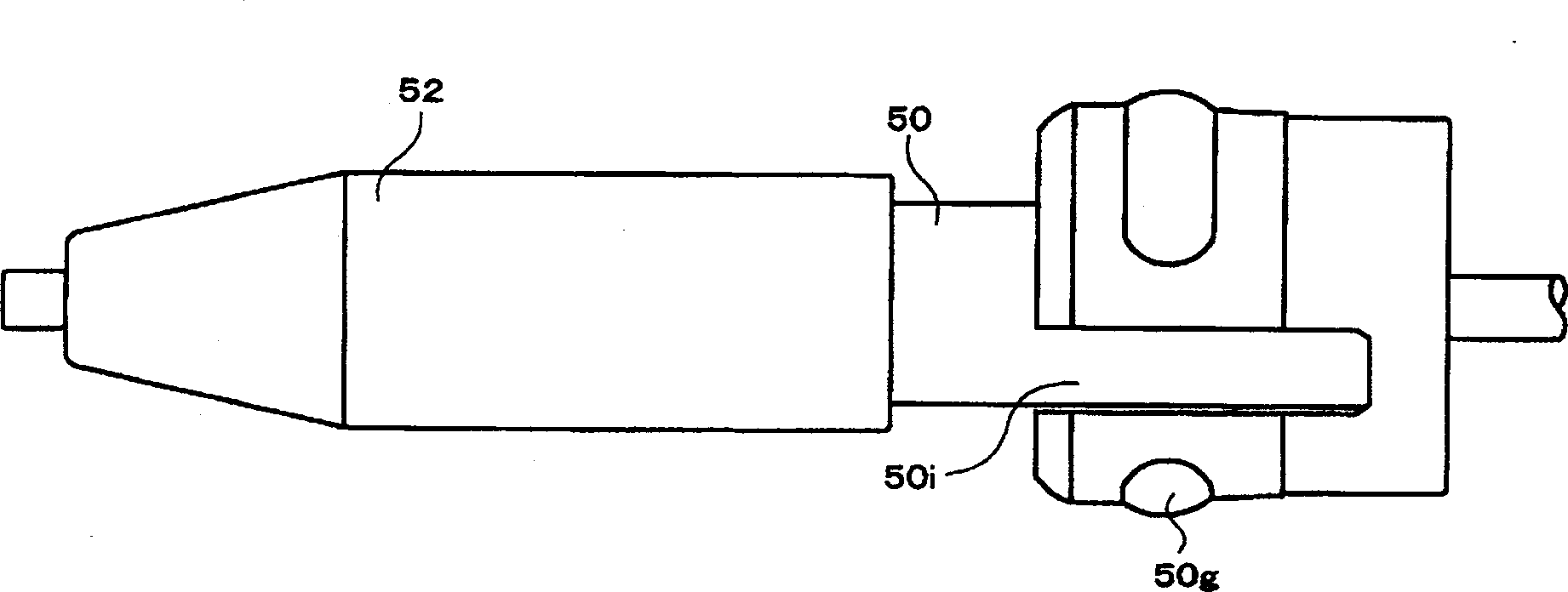
[0017] In the figure, the mechanical pencil mainly has a pen holder 10, a core feeding mechanism 20, a core holding part 50 and an operating part (omitted in the figure). The core-feeding mechanism 20 is arranged in the pen holder 10, and is used to clamp the lead and send the lead out; the core-holding part 50 is located at a position more forward than the core-feeding mechanism 20, and is used to maintain the through-through lead, and the operating part is used to Operate the core feeding mechanism to send out the lead core.

[0018] Penholder 10 is made of front axle 12, and the front axle taper end 14 that is threaded with front axle 12 and rear axle (omitted among the figures) constitute; These front axles 12, the front axle cone end 14 and the rear axle also can be made of integral parts, o...


PUM


Abstract

To provide a mechanical pencil, with the residual amount of a lead can be made very small. A slider 50 having a through hole, through which the lead passes, is provided at the side nearer the tip side than a lead delivering mechanism in a barrel so as to form collets 50e, which projects inward radially in order to hold the lead, at the tip part of the slider 50. At the rear end part of the slider 50, ribs 50f, which project radially in order to hold the lead, is formed. A consumed lead L1 is held by the collects 50e and a following lead L2 is held by the ribs 50f.

Description

technical field [0001] The invention relates to a mechanical pencil, in particular to a mechanical pencil which can effectively use the lead core and shorten the waste lead core. Background technique [0002] Existing mechanical pencils all have parts such as a pen holder, a core feeding mechanism, a core holding part and an operating part; The front side clamps the through lead core; the operating part is used to operate the core feeding mechanism to send the lead core out; usually, the lead core is clamped by the core feeding mechanism to prevent the lead core from moving. When writing, in order to make the lead protrude from the front end of the pen holder, the lead core is sent out by the core feeding mechanism through the operating parts. At this time, in order to allow the core holding part to clamp the lead core, when the lead core is sent out by the core feeding mechanism, only a certain amount of lead core should be sent out and not retreat together when the core f...

Claims


Application Information

Patent Timeline
Patent Type & Authority Applications(China)
IPC IPC(8): B43K21/027B43K21/033B43K21/22
CPCB43K21/033B43K21/22
Inventor 阴山秀平野口芳男
Owner KOTOBUKI & CO LTD
Learn More