Intervertebral implant

An implant, intervertebral technology, applied in the field of intervertebral implants, can solve the problem of impossibility, x-ray opacity

Inactive Publication Date: 2002-09-04
SYNTHES GMBH
View PDF1 Cites 19 Cited by
  • Summary
  • Abstract
  • Description
  • Claims
  • Application Information

AI Technical Summary

Problems solved by technology

[0003] A disadvantage of this known implant is its opacity to X-rays, which makes postoperative observation of the merging of the vertebral bodies impossible

Method used


Image

  • Intervertebral implant
  • Intervertebral implant
  • Intervertebral implant

Examples


Embodiment Construction

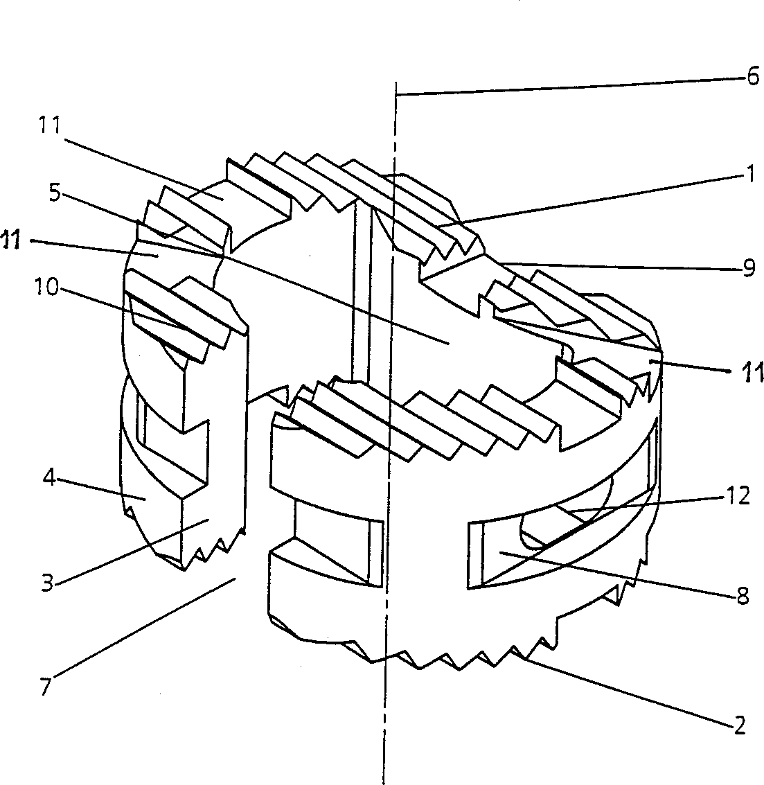
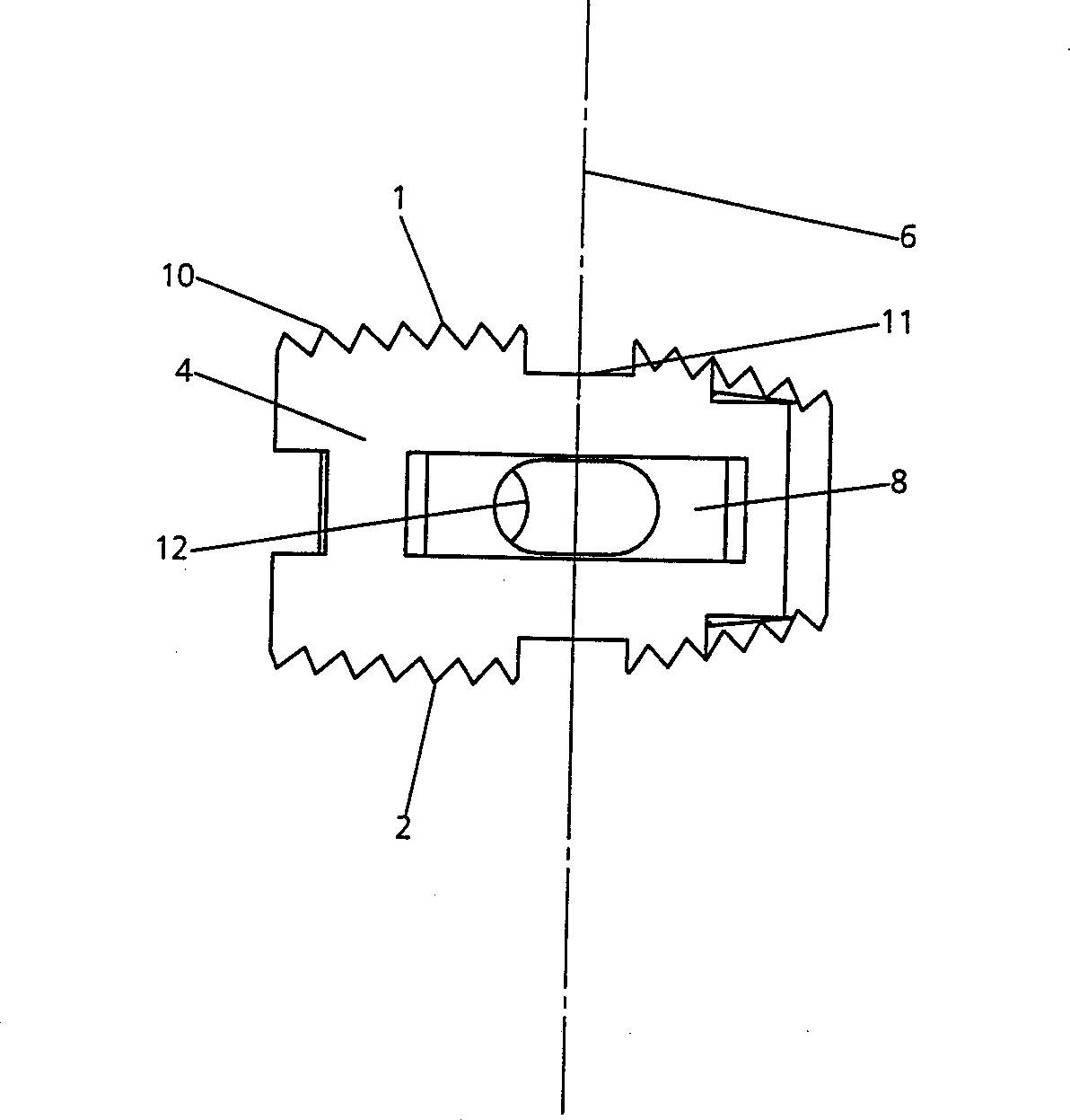
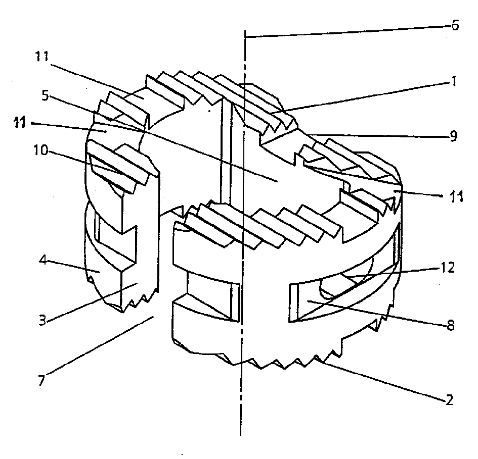
[0024] figure 1 and figure 2 The intervertebral implant shown has the shape of a hollow cylinder. It has a cover surface 1 , a base surface 2 , a hollow cylindrical wall 3 comprising an outer surface 4 and an inner surface 5 , and a hollow cylindrical central axis 6 .

[0025] At least ninety-five percent of the volume of the implant consists of an X-ray transparent material such as PEEK (polyaryletherketones). The material used must have a modulus of elasticity between 1 and 20 GPa. Preferably the modulus of elasticity is between 3 and 5 GPa.

[0026] The intervertebral implant also carries three markers (not shown) made of x-ray-opaque material (titanium or tantalum), which together account for at most 100% of the intervertebral implant. five percent of the volume. By total volume (100%) is understood the volume occupied by the material of the intervertebral implant, excluding the hollow space enclosed by the implant.

[0027] Both the cap surface 1 and the base surfa...


PUM

PropertyMeasurementUnit
elastic modulusaaaaaaaaaa
heightaaaaaaaaaa

Abstract

An intervertebral implant is shaped in the form of a hollow cylinder and has a cover face, a base face, a hollow cylinder wall with an outer lateral area and an inner lateral area, as well as a hollow cylinder central axis. The implant is formed at least 95 percent by volume of a radiolucent material which has a modulus of elasticity of between 1 and 20 GPa. Postsurgical observation is permitted by means of X-rays, and at the same time the implant has a high degree of biocompatibility.

Description

technical field [0001] The invention relates to an intervertebral implant according to the preamble of claim 1 . Background technique [0002] An intervertebral implant of this type is known from DE-A 196 15 938, which is made of an elongated metal plate and is therefore impermeable to X-rays. [0003] A disadvantage of this known implant is its X-ray opacity, which makes postoperative observation of the merging of the vertebral bodies impossible. Contents of the invention [0004] The present invention seeks to remedy the aforementioned disadvantages. It is therefore an object of the present invention to provide an intervertebral implant which allows post-operative observation by X-ray and which at the same time is characterized by a high degree of biocompatibility. [0005] The invention achieves this object by means of an intervertebral implant having the features of claim 1 . Furthermore, the relatively low modulus of elasticity of the X-ray transparent material gen...

Claims


Application Information

Patent Timeline
Patent Type & Authority Applications(China)
IPC IPC(8): A61L27/00A61B17/02A61F2/00A61F2/30A61F2/44A61F2/46E03C1/04
CPCA61B2017/0256A61F2/442A61F2/4611A61F2002/3008A61F2002/30131A61F2002/30158A61F2002/30187A61F2002/30777A61F2002/30784A61F2002/3082A61F2002/30904A61F2230/0013A61F2230/0026A61F2230/0034A61F2250/0098A61F2002/30593
Inventor 曼努埃尔·沙尔热罗姆·伯恩哈德康拉德·塔格威尔克
Owner SYNTHES GMBH
Why Eureka
Try Eureka