Spinning cup with one free end capable of being mounted with supporting spindle cap

A spinning cup and free end technology, which is applied in the field of supporting caps, can solve the problems of supporting caps falling off, splitting of supporting caps, thick wall of supporting caps, etc., so as to avoid axial vibration, keep the distance stable, easy-to-manufacture effects

Inactive Publication Date: 2002-09-25
RIETER INGOLSTADT SPINNEREIMASCHENBAU AG
View PDF1 Cites 4 Cited by
  • Summary
  • Abstract
  • Description
  • Claims
  • Application Information

AI Technical Summary

Problems solved by technology

When ceramic materials are used as the material for supporting the cap, due to the brittleness of the material and the press fit of the radial action, there is a danger of the sleeve supporting the cap being broken when it is pressed in
Furthermore, due to the temperature gradient and the different coefficients of thermal expansion between the supporting cap and the journal, when the rotor shaft and the supporting cap are running and heated, tear

Method used


Image

  • Spinning cup with one free end capable of being mounted with supporting spindle cap
  • Spinning cup with one free end capable of being mounted with supporting spindle cap
  • Spinning cup with one free end capable of being mounted with supporting spindle cap

Examples


Embodiment Construction

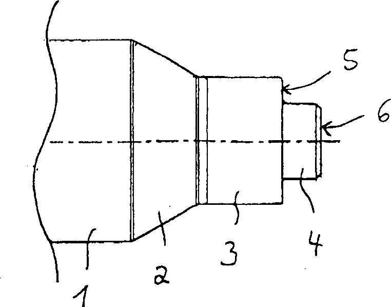
[0029] figure 1 The free end of the shaft 1 of the rotor of an open-end spinning machine is shown. The free end of the spinning cup shaft 1 is located on the side opposite to the spinning cup, and has a conical portion 2 with a gradually decreasing shaft diameter, a cylindrical portion 3 and a shaft-diameter portion 4 . The cylindrical part 3 has a front bead 5 which serves as a stop or facing surface for a wearing cap 7a, b, c, d. Furthermore, the shaft-shaped part 4 has a planar front side 6 which also serves as an alignment or stop surface for the wear cap.

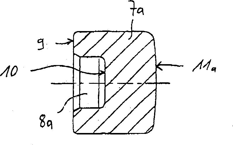
[0030] A first embodiment of the worn cap 7a is in figure 2 shown in . The outer diameter of the wear cap 7a corresponds to the outer diameter of the cylindrical portion 3, and the shaft-shaped portion 4 of the shaft 1 can be completely inserted into the substantially cylindrical recess 8 of the wear cap 7a. Its back side, ie the annular front side 9 of the wear cap 7 a, serves as a stop or opposite face to the be...


PUM


Abstract

The invention relates to a free-end spinning cup, which has a shaft (1) on which a support cap (7d) can be mounted on the free end of the shaft, the invention also relates to such a support cap, and the manufacture of a free end The method of spinning cups. According to the invention, the free-end spinning cup is designed such that the shaft (1) has a front facing surface (5, 6), and the supporting cap (7d) has an opposite facing surface (9, 10) for supporting The caps (7d) are aligned with respect to a plane perpendicular to the axis of the rotor and/or have inclined counter faces for aligning and coaxially aligning the supporting caps (7d) with the shaft (1).

Description

technical field [0001] The invention relates to an open-ended spinning cup, which has a shaft, on the free end of which a support cap can be mounted, and also to a support cap for use therein. Background technique [0002] In a known rotor shaft (DE 40 20 411 A1), a supporting cap can be mounted on a shoulder or a support at the free end of the shaft. When the spinning cup is running, the supporting spindle cap presses the free end on a ball, and the rotation of the supporting spindle cap drives the ball, so that the lubricating medium in the lubricating medium groove is added between the spherical surface and the supporting spindle cap surface. The outer surface of the journal serves as a guide surface for centering and aligning the support cap, and the journal sits in the support cap to a depth of more than half of the total support cap depth. At the same time, the outer peripheral surface of the journal forms a press fit with the inner surface of the supporting cap, so t...

Claims


Application Information

Patent Timeline
IPC IPC(8): D01H4/10D01H4/12F16C17/08
CPCD01H4/12F16C17/08F16C2340/18
Inventor E·苏乐M·克纳宝W·斯特拉瑟
Owner RIETER INGOLSTADT SPINNEREIMASCHENBAU AG
Why Eureka
Try Eureka