Apparatus and method for removing contaminants from fine grained soil, clay and silt
A technology of equipment and polluting particles, which is applied in the field of equipment for removing pollutants and pollutants, and can solve problems such as limited effect.
- Summary
- Abstract
- Description
- Claims
- Application Information
AI Technical Summary
Problems solved by technology
Method used
Image
Examples
Embodiment 1
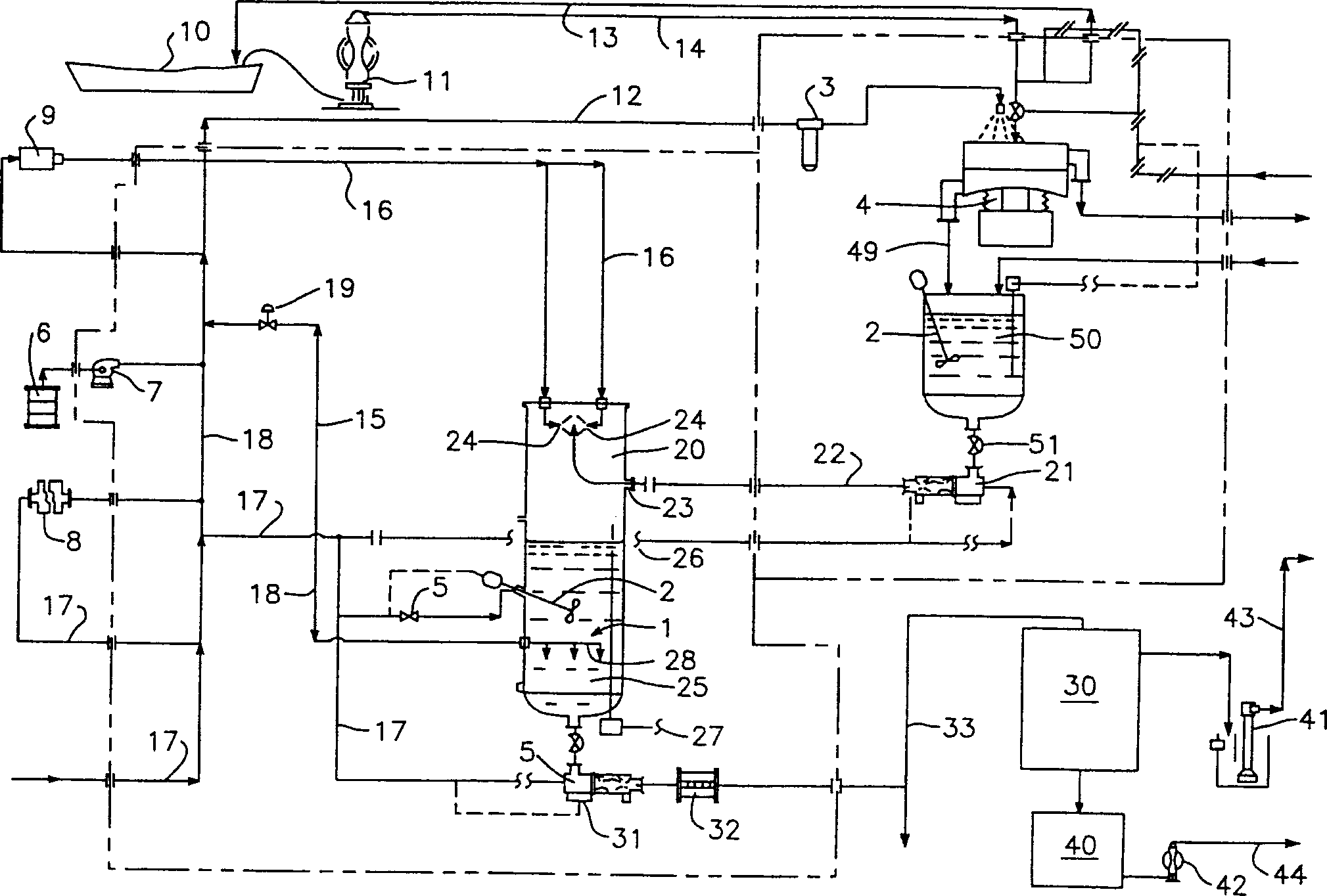
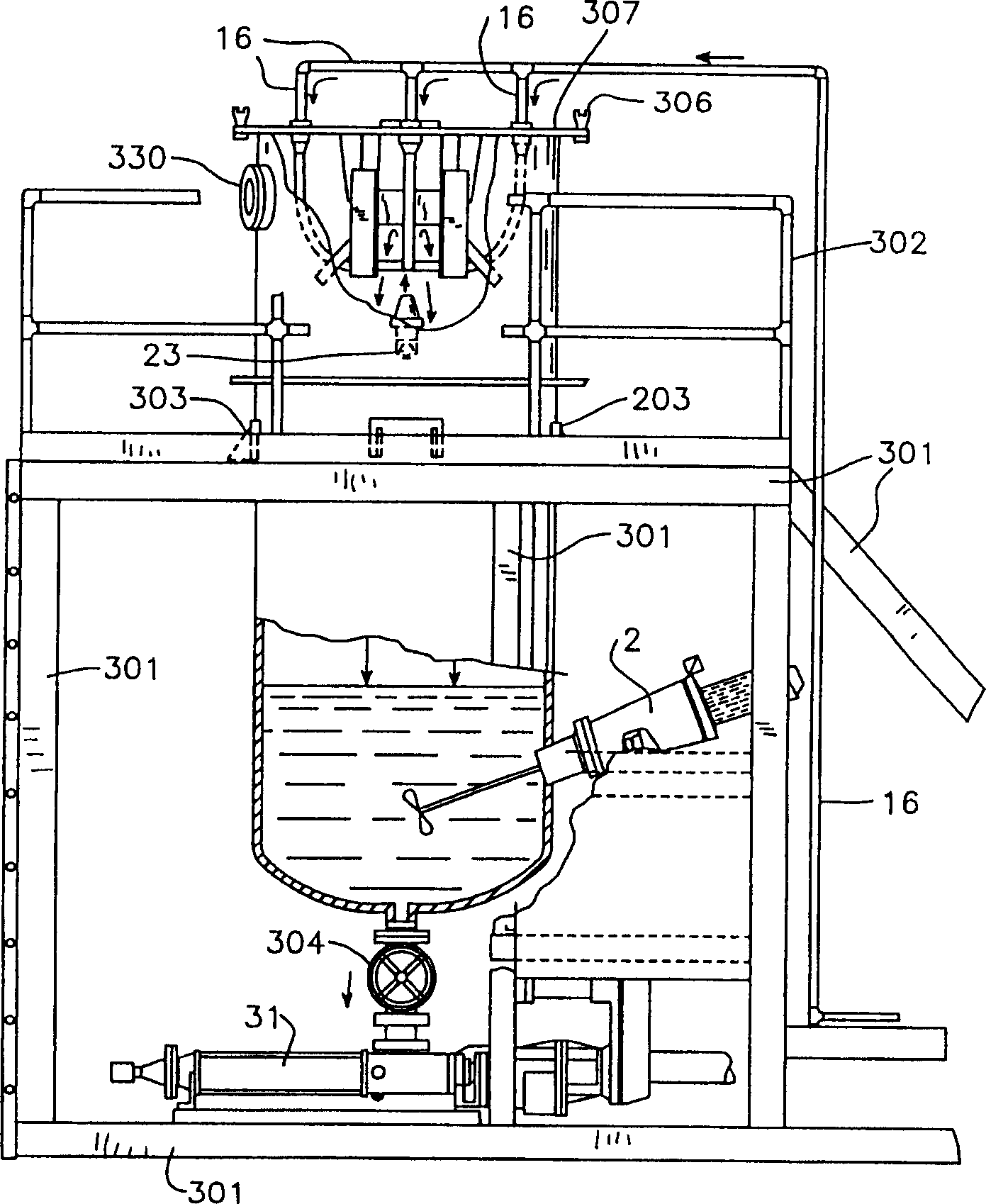
[0094]The equipment constructed for this example was a continuous flow unit for cleaning fines and clays. Utilizing a series of collision cells working in parallel, throughputs of up to 80 to 100 cubic yards per hour can be achieved.
[0095] Sediments contaminated with polyaromatic hydrocarbons (PAH) above 4000ppm were selected for cleaning. The contaminated sediments were predominantly (81%) medium silts with an average particle size of less than 38 microns. Sediment is treated first to separate large particulate material. Transfer the large particle material to a standard large particle washer for disposal. The material passing through the iron grid screen flows to the pulverizer and then enters the pretreatment tank. The pulverized material is mixed, heated and mixed with water and biosurfactant chemicals. This forms the slurry.
[0096] The slurry is then sent to a vibrating screen separator, which screens the particles into two groups. Material larger than 0.5 mm i...
Embodiment 2
[0113] In this embodiment, particles above 50 mesh and below 50 mesh are selected. In this example, the temperature of the cleaning fluid was maintained at 100°F. The number of nozzle devices used was four. The intersection angle of the plane defined by the nozzle discharge flow and the input flow was maintained at 135 degrees.
[0114] Tests were conducted at discharge pressures of 6000 psi, 8000 psi and 12000 psi for each nozzle. It has been determined that when the particle size is less than 50 mesh and the discharge pressure of the nozzle device is 8,000 to 12,000 psi, the decontamination efficiency of 99% is generated for particles passing through 200 mesh. See Table 1.
[0115] Sediment Cleaning Efficiency
[0116] In this embodiment, the number of nozzles used is 4, and the pressure of each nozzle discharging the cleaning liquid is 6000 psi. The discharge angle between the plane defined by the discharge flow of the nozzle arrangement and the input flow is ...
Embodiment 4
[0120] In this embodiment, the angle of intersection between the plane defined by the nozzle discharge flow and the incoming flow is adjusted to be 45 degrees relative to the mud flow. The discharge pressure of each nozzle was fixed at 6000 psi in this example. The temperature of the cleaning solution was maintained at 100°F.
[0121] Sediment Cleaning Efficiency
[0122] In this example, the discharge pressure of the nozzle assembly was maintained at 6000 psi. The temperature of the cleaning solution was maintained at 100°F.
[0123] Sediment Cleaning Efficiency
[0124] In this embodiment, the discharge pressure of the nozzle assembly is also maintained at 6000 psi. The temperature of the cleaning solution was maintained at 100°F. In this example, the angle between the discharge point of the nozzle assembly and the input flow was increased from 90° to 135°, and the increase in pollutant removal rate was less significant compared to the results obtained...
PUM
| Property | Measurement | Unit |
|---|---|---|
| The average particle size | aaaaa | aaaaa |
Abstract
Description
Claims
Application Information
 - R&D
- Intellectual Property
- Life Sciences
- Materials
- Tech Scout
- Unparalleled Data Quality
- Higher Quality Content
- 60% Fewer Hallucinations
Browse by: Latest US Patents, China's latest patents, Technical Efficacy Thesaurus, Application Domain, Technology Topic, Popular Technical Reports.
© 2025 PatSnap. All rights reserved.Legal|Privacy policy|Modern Slavery Act Transparency Statement|Sitemap|About US| Contact US: help@patsnap.com


