Apparatus and method for removing contaminants from fine grained soil, clay and silt

A kind of equipment and technology for polluting particles, which can be used in equipment for removing pollutants and in the field of removing pollutants, which can solve problems such as limited effect.

Inactive Publication Date: 2007-04-25
BIOGENESIS ENTERPRISES
View PDF8 Cites 0 Cited by
  • Summary
  • Abstract
  • Description
  • Claims
  • Application Information

AI Technical Summary

Problems solved by technology

As can be seen from Table 8, increasing the angle between the nozzle flow and the sediment inflow by about 30 degrees has limited effect

Method used


Image

  • Apparatus and method for removing contaminants from fine grained soil, clay and silt
  • Apparatus and method for removing contaminants from fine grained soil, clay and silt
  • Apparatus and method for removing contaminants from fine grained soil, clay and silt

Examples


Embodiment 1

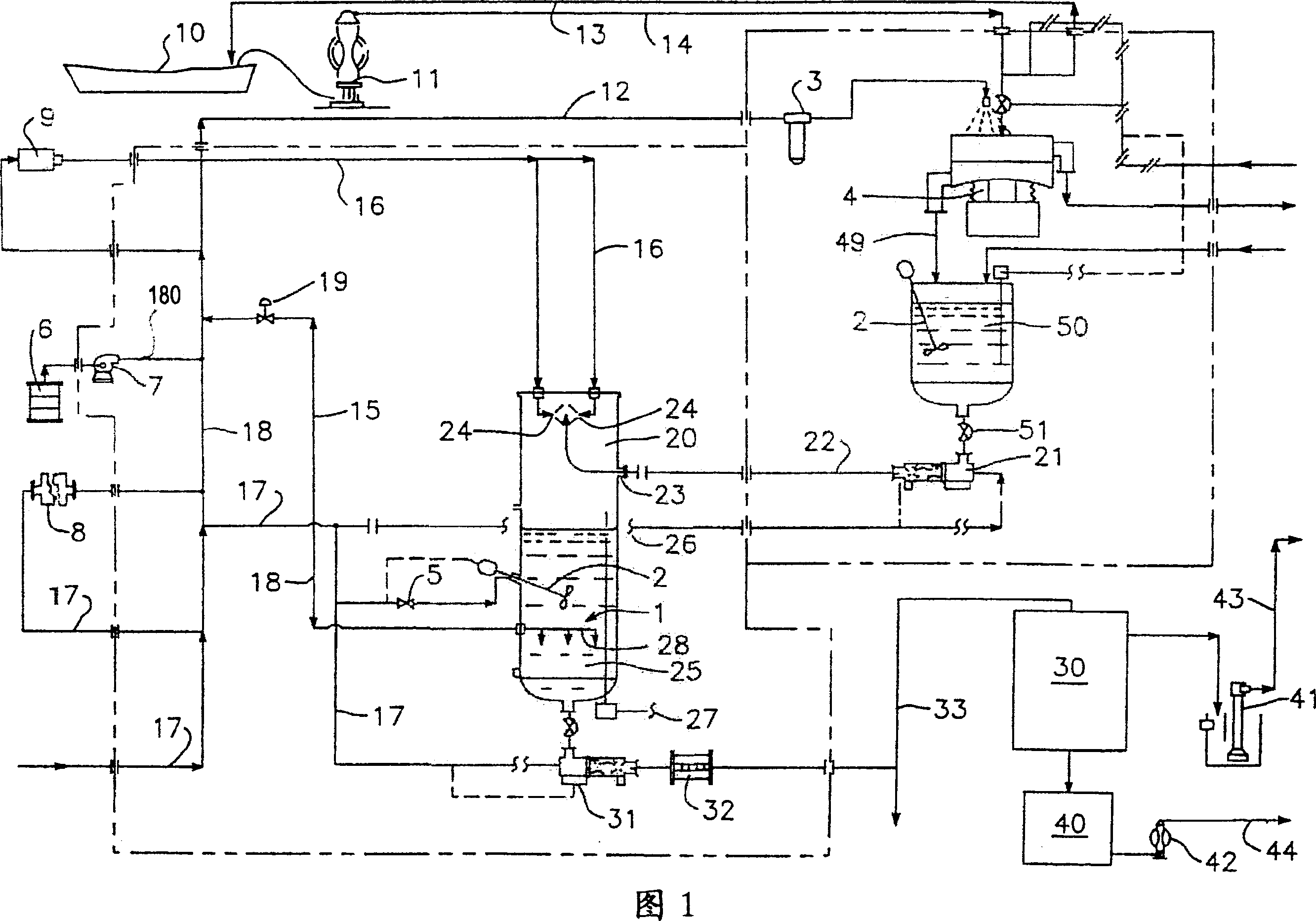
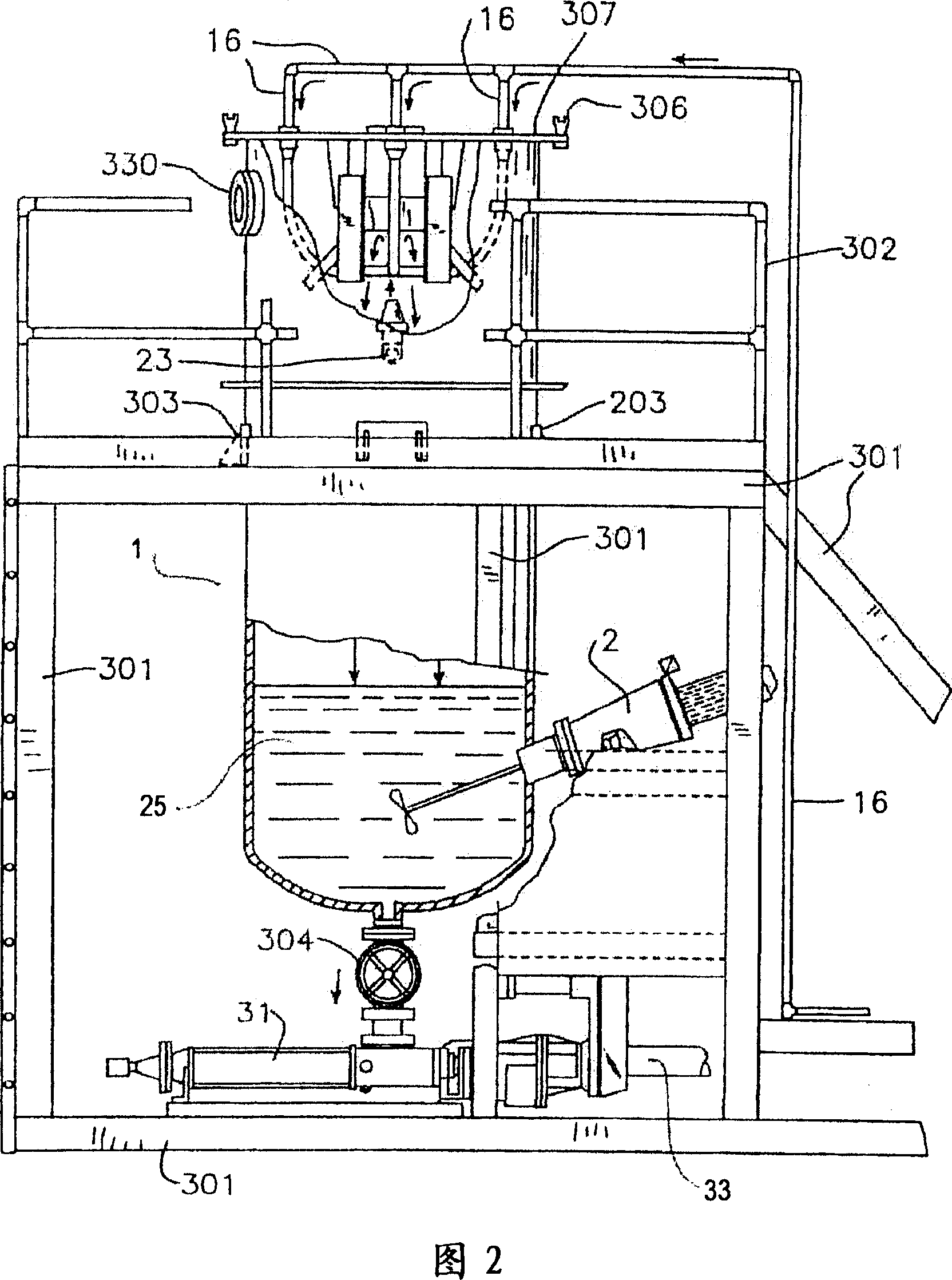
[0101] The equipment constructed for this example was a continuous flow unit for cleaning fines and clays. Utilizing a series of collision cells working in parallel, throughputs of up to 80 to 100 cubic yards per hour can be achieved.

[0102] Sediments contaminated with polyaromatic hydrocarbons (PAH) above 4000ppm were selected for cleaning. The deposition of the pollution

[0103] Most of the material (81%) is medium silt with an average particle size of less than 38 microns. Sediment is treated first to separate large particulate material. Transfer the large particle material to a standard large particle washer for disposal. The material passing through the iron grid screen flows to the pulverizer and then enters the pretreatment tank. The pulverized material is mixed, heated and mixed with water and biosurfactant chemicals. This forms the slurry.

[0104] The slurry is then sent to a vibrating screen separator, which screens the particles into two groups. Material ...

Embodiment 2

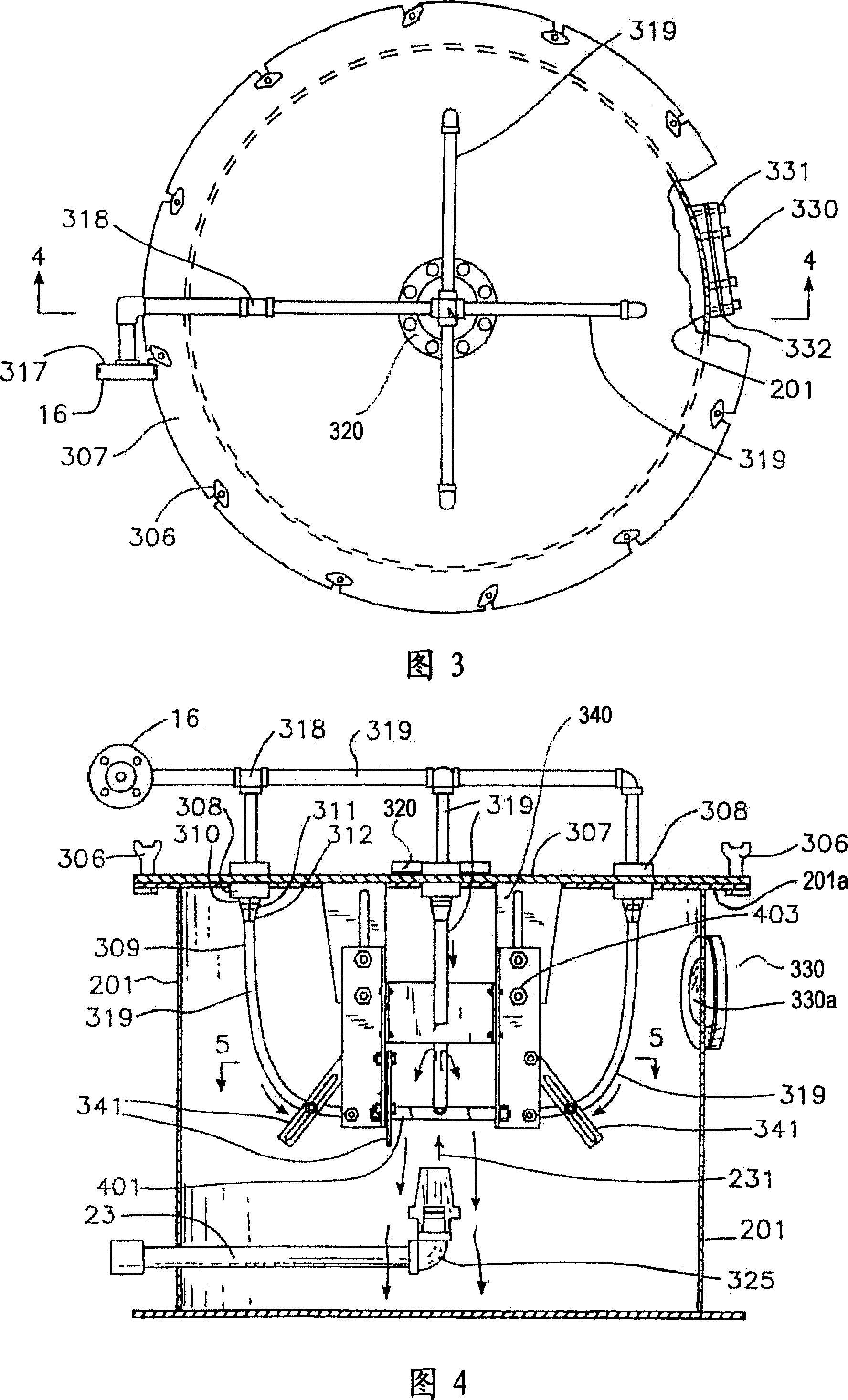
[0121] In this embodiment, particles above 50 mesh and below 50 mesh are selected. In this example, the temperature of the cleaning solution was maintained at 100°F (37.78°C). The number of nozzle devices used was four. The intersection angle of the plane defined by the nozzle discharge flow and the input flow was maintained at 135 degrees.

[0122] Tests were conducted at discharge pressures of 6000 psi (41.4 MPa), 8000 psi (55.2 MPa) and 12000 psi (82.7 MPa) for each nozzle. It has been determined that when the particle size is less than 50 mesh and the discharge pressure of the nozzle device is between 8000 (55.2MPa) and 12000psi (82.7MPa), the decontamination efficiency of 99% is generated for particles passing through 200 mesh. See Table 1.

[0123] Table 1

[0124]

Embodiment 3

[0126] In this embodiment, the number of nozzles used is 4, and the pressure of each nozzle discharging the cleaning liquid is 6000 psi (41.4 MPa). The discharge angle between the plane defined by the discharge flow of the nozzle arrangement and the input flow is maintained at 90 degrees.

[0127] In this example, the temperature of the cleaning solution was tested in a range around 100°F (37.78°C). These temperatures were less effective for both large and small particles (see Table 2).

[0128] Table 2

[0129] Sediment Cleaning Efficiency

[0130] It was determined that when removing contaminants from the oils used in this example, the temperature must be maintained between 100 and 160°F ((37.78°C to 71.11°C) to achieve 99% efficiency on particles passing through 200 mesh. This Other applications of the equipment may use higher or lower cleaning fluid optimum temperatures, depending on the type of contaminant and the average size of the particles being treated in...


PUM

PropertyMeasurementUnit
diameteraaaaaaaaaa
diameteraaaaaaaaaa
diameteraaaaaaaaaa

Abstract

The disclosure of this application relates to a method and apparatus for removing a variety of contaminants from soil, sediment, fine sand and clay. The disclosure describes an apparatus in which contaminated material that is comprised of particles having a size less than about 5 mm in diameter are injected from a nozzle (231) into a zone of discharge from one or a number of nozzles (500). These nozzles (500) are positioned to discharge liquid or cleaning fluid at a pressure from about 2000 psi to about 20,000 psi. The cleaned material is then collected and separated into liquid and solid phases. The solids, when cleaned by the use of this apparatus, can then be returned to the site without danger of contamination of the surrounding area and no disposal costs are incurred for disposition of contaminated soil.

Description

[0001] The present invention relates to apparatus and methods for the efficient removal of pollutants from fine-grained soils, clay silts and sediment particles. Summary of the invention [0002] The present invention relates to an apparatus for removing pollutants from soil, clay and sediment particles which may be found in areas contaminated by eg industrial chemicals, oil etc. The device utilizes a liquid to effectively remove pollutants from the surface of soil particles. The device is capable of creating a zone of extreme turbulence through opposing high-pressure jets directed at the same point. A slurry feed unit injects soil-contaminated slurry into the discharge area of ​​the nozzle unit. Contaminants are removed from the soil particles in the slurry as they pass through the intersection of the sprinkler and nozzle discharge streams. In this way, the contaminants are separated from the surface of the soil particles, leaving particles substantially free of contaminant...

Claims


Application Information

Patent Timeline
Patent Type & Authority Patents(China)
IPC IPC(8): B08B3/02B09C1/00B03B5/00B09C1/02B09C1/10C02F11/00
CPCB09C1/02B09C1/10B08B3/02
Inventor 墨森·C·阿米兰
Owner BIOGENESIS ENTERPRISES
Why Eureka
Try Eureka